This thread has been locked.

If you have a related question, please click the "Ask a related question" button in the top right corner. The newly created question will be automatically linked to this question.

ucc27532 enable pin in full bridge inverter

Other Parts Discussed in Thread: UCC27532

Hi,

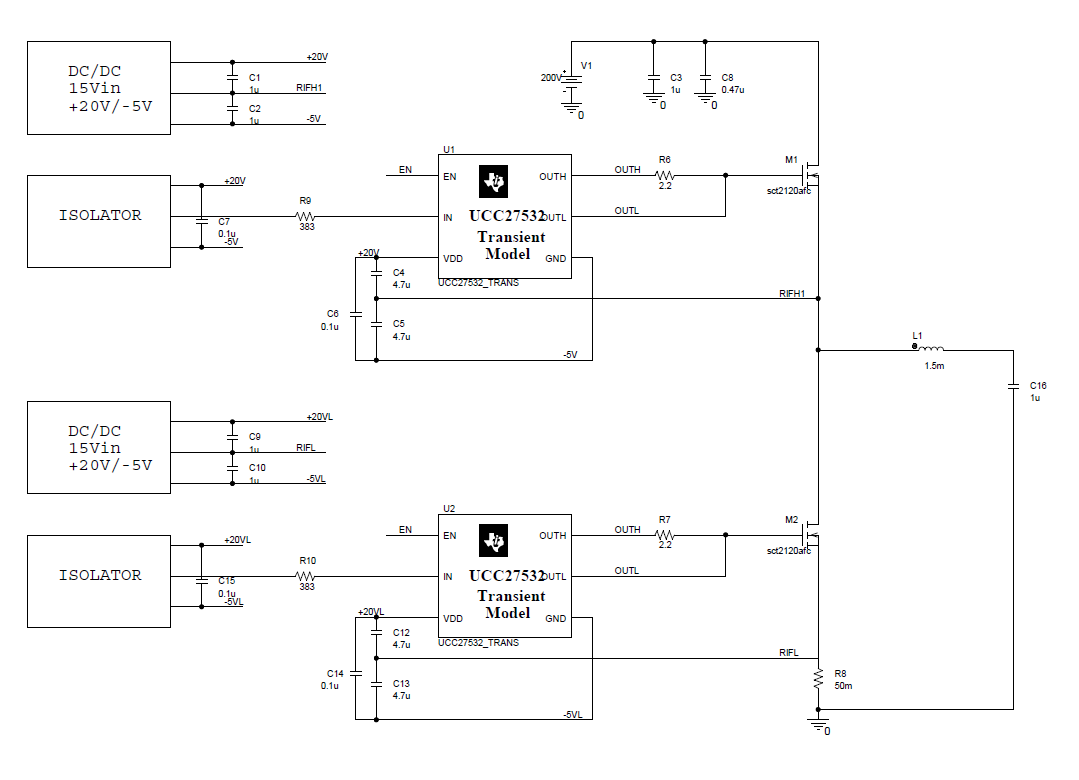
i've realized a full bridge pwm inverter with ucc27532 mosfet/sic driver.

In figure below only half bridge is shown.

The features of the pwm inverter are:

Vbus=250V

Vout=150Vac

Iout=1A

Fsw=25KHz

The first problem i've encountered is that without a large value resistor on input pin, the driver became very hot (70° temp rise). Is this problem known?

The second problem is that leaving floating the ENABLE pin only on high side mosfet driver the input pulses are not executed properly on OUTH and the driver is disabled improperly. That thing causes unexpectedly mosfet driving. That fact is not present on low side driver. 

A 4k7 pull-up on EN pin to +20V seems to solve the problem explained.

Could you help me in understanding this thing? Is there any error in my schematic?

Thanks a lot

  • Hello Frantic,

    For the 1st problem you mention, is the 383 Ohms shown on the schematic, the increased resistance that solves the problem with temperature rise? What the increased resistance will result ,is additional HF filtering on the IN pin from the pin capacitance and the increased resistor value. Did the output have any HF transients on turn on or turn off before the resistance increase?

    For the second question: High side output driver behavior until external pullup resistance added to EN pin. The internal pullup resistance is 500k Ohms to 5.8V internal to the IC to limit the disable current required to a low value. The high side dv/dt during switching likely required increased pull up current to avoid common mode noise from causing the EN pin to result in intermittent behavior.

  • For the first problem the previous resistor was 33ohm... in order to mantain the ic to ambient temperature i have to increase the resistor value until 383 ohm. Anyway if i try to drive the driver without load (mosfet in this case) the temperature goes high without that resistor.

    For the second question you confirm me the need for a pull-up?

    Is it better a pull-up resistor or a short-circuit to +20V?

    Thanks a lot
  • For the question of pull-up resistor or short circuit to +20V for the enable pin. For the function both a short connection to 20V and a pull up resistor will work. The advice would be to use the pull up resistance for the enable as you have now. The reason would be if there is a transient, esd surge etc, that caused the 20V to be higher than normal, the resistance in series with the enable pin will limit the current to prevent damage to the pin.

    I would suggest leaving the pull-up resistance as you have now.