This thread has been locked.

If you have a related question, please click the "Ask a related question" button in the top right corner. The newly created question will be automatically linked to this question.

UCD3138 - Topology For Bridgeless PFC

Hi,

The bridgeless PFC design stated in SLUA713 is using triangular mode to drive DPWM.

Despite it is using CT for measuring input current, any other reasons why triangular is used in this design?

If the CT are replaced by a shunt resistor to sense input current on the neutral line in a bridgeless PFC,

is it still better to use triangular mode instead of others topologies? Why?

CF. Lee

  • Hi CF,

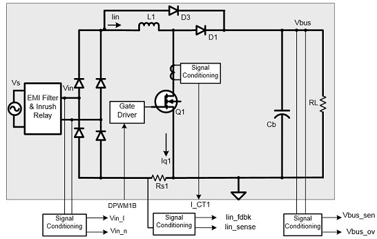
    When you use CT to sense the current, it can only sense inductor rising current, this is only partial of the total current, while our goal is to control the total current, so you need to find out the total current through this partial current. By using triangular modulation, we can sense at the middle point of this rising current, and by knowing Vin, Vout and duty, we can calculate the whole current. Triangle modulation is not necessary, as far as you can sense at the middle of the rising current.

    What do you mean put shunt on neutral line? Do you mean put a shunt in the ground line? The answer is no, you cannot use shunt in this semi-bridgeless PFC, because not the total current go through this shunt, there are some current returning to AC source through the other inactive phase, so your feedback signal is not accurate.  

    Regards,

    Bosheng Sun


  • Hi BoSheng,

    What i mean shunt resistor is like Rs1 in the diagram above. The current flows through Rs1 should be the total current?

    If the current flowing through Rs1 represents a good feedback signal, is there any other reasons why shunt could not be put in a semi-bridgeless design?

    CF. Lee

  • Hi CF,

    In semi-bridgeless PFC, only once phase is active in every half AC cycle. For example, when L1, Q1 is active, partial of its returning current go through shunt Rs1 then back to AC source, but the other partial returning current will go through Q2 body diode, L2 then back to AC source, Rs1 does not sense the total current, therefore shunt cannot be used in this topology.

    Regards,

    Bosheng Sun


  • Hi BoSheng,

    Thanks, now i understand why triangular mode is used when using CT, and why shunt on the ground line doesnt work for a semi-brigdeless PFC.
    So if i really dont want to use CT as the current sensor, the only way should be replacing the CT with a shunt resistor, that i can sense the input current at both positive cycle and negative cycle. While i still have to use triangular mode as the current through the shunt is partial only.

    CF. Lee