This thread has been locked.

If you have a related question, please click the "Ask a related question" button in the top right corner. The newly created question will be automatically linked to this question.

Bias input to TPS74401RGWR

Other Parts Discussed in Thread: TPS74401, TPS7A84, TPS7A85

Hello,

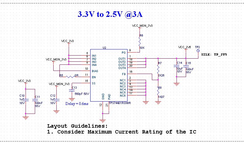
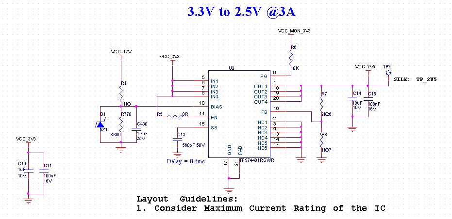
We are using  TPS74401RGWR to generate 2.5V from 3.3V and we are giving 3.3V as bias voltage. But as i seen in datasheet it is telling that we need to give Vbias=Vout+1.6V. If we give same input votge to bias how it functions please explain me

Regards,

Prasanna G

  • Hi Prasanna,

    If the dropout requirement is not met, the LDO would operate in the dropout region. This region is described in section 7.4.2 of the datasheet. Effectively the LDO will operate like a resistor with the output following the input. AC performance will be severely degraded as well in the dropout region. For TPS744 both the bias dropout and input dropout specifications must be met to allow for normal, regulated operation.

    Very Respectfully,
    Ryan
  • Hello Ryan,

    I have gone through the datasheet , So my design attached is entirely wrong know.

    Can it possible to generate 2.5V@3A from 3.3V @ 8A  since  I am not able to run the web bench for 2.5V in TPS744.

    I am not cleared with dropout region , Can you please explain me in brief.Also can you  give me suggestion to generate2.5V from 3.3V .

    Regards

    Prasanna G 

  • Hi Prasanna,

    You are able to generate 2.5V at 3A with TPS74401. You have adequate headroom from Vin to Vout with your current design. You will simply need to provide a Bias rail of 4.12V or higher in order to satisfy the Vbias dropout requirement.

    Alternatively TPS7A84 would be able to work in your application without a bias rail.

    Very Respectfully,
    Ryan
  • Hello Ryan,

    Thank you for the valuable information.

    We don't have any 5V regulated output in our design, we only have 12V regulated output. Is it possible if i give 5V Vbias using voltage divider to 12V .

    I am too curious in the Requirement of Vbias voltage, Can you please explain me how these Vbias used in internal circuit of the LDO IC since iam confused of these LDO concept bec of many document with different explanation..

    Thankfully,
    Prasanna G
  • Hi Prasanna,

    You can divide down the 12V rail if you would like. It may be worth investigating TPS7A84 though. The TPS7A84 would not require a bias rail under your conditions. As a result it could save you components and board space.

    Vbias is used to power the internal circuitry of the LDO (error amplifier, etc). For LDOs that do not have a bias rail, this circuitry is powered off of the input to the LDO. The advantage of using a bias rail is that it decreases the dropout of the LDO. As a result, a given application can provide a smaller amount of headroom and dissipate less heat.

    In your application, you are providing enough headroom that you do not require a bias rail; however, TPS74401 powers the internal circuitry from BIAS. As a result, you must still provide the bias rail. TPS7A84 is able to power the internal circuitry from Vin or Vbias depending on the conditions. In your conditions, you would not need to provide a bias rail and TPS7A84 would still function in the normal operating region.

    Very Respectfully,
    Ryan
  •  Hello Ryan,

    Now am cleared with your information and got the concept of LDO but Iam once again with some more query!.

    So am planing to retain TPS74401RGWR in our design and providing bias voltage 5V through volage divider from 12V rail as in attached image.

    But i have read in datasheet like "V bias must be an independent supply".

    Can you please cross verify my design and suggest me for any change if required.

    Thankfully,
    Prasanna G

  • Hi Prasanna,

    Your schematic looks ok.

    The statement "Vbias must be an independent supply" is in the detailed design procedure section of the datasheet. This section is meant to illustrate an example design which has the requirements stated in the previous section (8.2.1.1 Design Requirements). Due to the design requirements in the example, it was determined that Vbias must be independent of Vin. This is actually very similar to your application where you are not able to tie Vbias to Vin because of the dropout specs.

    Very Respectfully,
    Ryan
  • Hello Ryan,

    Am not getting the output for above circuit, Can you please help me.

    Regards,
    Prasanna G
  • Hi Prasanna,

    The problem with the resistor divider is that you need to be able to supply the Ibias requirement of 4mA max in the datasheet - the 11k resistor is too large in magnitude. You need to reduce the impedance of the 5V rail by lowering the R1 and R2 values.

    Also it seems like you showed some confusion on dropout operation. The problem is that an LDO in normal saturation acts as a near ideal current source - for any Vin you get a fixed Vout. When Vin is too close to Vout (dropout) the LDO puts it's pass device hard in the linear region (for FETs), making it a resistor governed by the RDson of the FET. A more clear explanation can be found in the TPS7A85 datasheet for dropout and other LDO specifications.

    Regards,
    David