This thread has been locked.

If you have a related question, please click the "Ask a related question" button in the top right corner. The newly created question will be automatically linked to this question.

Output Current TLC59116

Other Parts Discussed in Thread: TLC59116, TLC5916

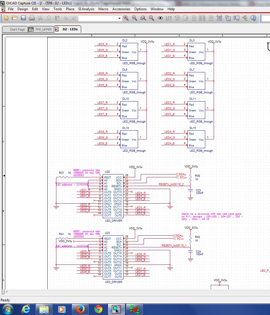
I want to know if the tlc59116 have a maximum of 100 mA for each OUTPUT of 100 mA for all OUTPUT.

I use 14 output lines with 20 mA leds 


How I can calculate the disipate power in the Rext


Thank you! Sorry for my english


Alexandre Marcotte

Student at the University Of Sherbrooke

  • TAlexandre,

    The TLC59116 can support up to 120mA per channel.  14 channels each at 20mA is easily done by the TLC59116.

    The REXT power can be calculated from the IREF and VREF.  The "Adjusting Output Current" section in the data sheet shows this.

    VREF = 1.26V * VG (The Voltage Gain - VG - default is 0.992) so, VREF = 1.25V

    IREF = VREF / REXT

    IOUT = IREF * 15 * 3^(CM-1);  The Default CM is 1, so IOUT = IREF * 15.

    For 20mA per channel, IREF = 20mA / 15 = 1.33mA.

    P = IREF * VREF = 1.25V * 1.33mA = 1.6mW

    Your English was quite sufficient.

    Regards,

    Dick

  • Thank you for your quick support.

    It very appreciated. My question has been answered well.


    Alexandre

  • Hi Dick,

    I do have a little problem with the TLC5916. With your experience, I hope you can give me some hint.

    The REXT I usedfor the circuit is 180 Ohms and according to the specification written in the data sheet, I should have about 100 mA per channel in theory. There are 6 channels outputs on the IC. I linked them in pair to obtain 200 mA in total for each channel pair. For each channel pair, I connected a series of 9 LEDs and supply voltage for the LED network is 18V. With this setup, I must have about 20mA current in each network. I can control each channel ON / OFF  or turen them all ON/ OFF by microcontroller.

    This circuit work almost perfectly, except one thing: the current at each channel pair I measured was just over 1mA. Therefore, the LEDs  were so dim. 

    Do you ave any suggestion of what the problem was?

    Thanks in advance.

    Kind regards,

    Nghia

    PS. You may contact me via the email: h.nguyen@ecu.edu.au

  • Nghia,

    I understand you have fixed the issue with your board.  The LED Voltage (18V) connection was not sufficient.  After fixing it, your board works well now.

    In the future for problems like this, some things to check include:

    Looking at scope current with a scope to verify PWM dimming is not causing low brightness;

    Verify the forward voltage (VF) of the LEDs to ensure that the series combination does not go beyond the LED supply;

    Verify REXT with a meter.

    Regards,

    Dick

  • Hi Dick,

    One more issue.

    In our design, we connect 8 tri-color LEDs to the driver, each color to separate pin.

    In our test design all LEDs are configured in same way.

    When we power up the board, 2 leds out of 8, have 1 color, out of 3 lighting but very weak.

    We have verified all board related issues, but nothing wrong there. At other LEDs, when I touch their pins with scope probe, they also start lighting very weak.

    What might cause such issue?

    Thank you in advance,

    Michael

  • Michael,

    I think you are seeing very small amounts of leakage.  If your probe is 1MOhms and your VLED is 5V, you may get 5V/1M or 5uA which is enough to get some light from the LED.

    Is it always the same color that's turning on?  That could be related to the amount of leakage and whether it is enough to see the light.

    Any contamination on the board could also create a path to ground.

    Regards,

    Dick

  • Hi,

    Its always the same color on the same LEDs, but between LEDs different colors lights.

    We thought about contamination before and carefully cleaned the PCB. Its just from the factory, so, I dont think PCB has any failure.

    Anyway, there are big GND plane just near some LEDs pins...

    What can be possible solution for such behavioral? May be weak pullups?

    Any other suggestions?

    Michael

  • Michael,

    Can you tell me the exact TLC59xx device you are using?  It might help me with my review.  Can you send me the LED part number?  If possible a screen shot of the TLC / LED schematic would also be helpful.

    It must be leakage, we need to determine the source.

    Regards,

    Dick

  • Hi Dick,

    The driver PN is TLC59116IPWR. The LED PN is SMLP34RGB2W

    Attached are relevant part of DSN and layout.

    Please, note, the LEDs are located in the middle of capacitive touch button. However, we followed all the rules and the buttons works pretty well.

    Please, advice,

    Michael

  • Michael,

    Thank you for the information.  I have a much better understanding of how you are using the TLC59116.

    The schematic is very clear.  It shows a 1kOhm resistor on REXT which will give about 18.75mA per channel.  The LED datasheet shows ABS MAX current of 10mA per channel with only 50% of that if multiple channels are on.   

    The layout looks very clean.  

    Have you changed any components to see if the LEDs with weak lighting follow the TLC59116 or the LED?  Does the weak lighting begin with the first power up or does it occur after some time?  

    Regards,

    Dick

  • Hi Dick,

    We didnt try to replace anything yes. I agree its good idea...

    The issue begins immediately after power on.

    Regards,

    Michael

  • Is there any solution to adjust the Output current for all 16 output pins depending on the Rext?

    I build a 5x5x5 LED RGB Cube , it all works fine.

    But now I set up the switching frequency (speed )to generate a still standing figure  for example a Cube or an character( above 50Hz) .

    Now my problem is that the brightness of the LEDs are not so bright as it is at low  switiching frequency. 

    I just set all PWM values to 0xff also I tested direffrent configuration in Register 1C IREF  but the only thing that

    changed was the voltage reference from 1,23V to 0,318V.

    In order to have a variable output current , I have connected an adjustable resistor (potentiometer) to pin REXT.

    Perhaps someone have  a good idea to solve  problem.

    If you want I can post my schematic. (I am using a TLC59116PWR)

    Regards

    Tobias