This thread has been locked.

If you have a related question, please click the "Ask a related question" button in the top right corner. The newly created question will be automatically linked to this question.

LM3150 changes Output Frequency while operating

Other Parts Discussed in Thread: LM3150

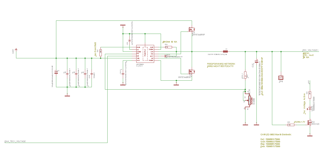
I got a little big Problem with LM3150:

While operating for like 2 Hours at constant Output Voltage and constant output current it happens that the switcher changes output Frequency from >100kHz to
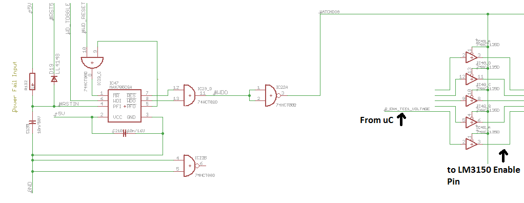
10kHz. You can can hear the inductor start making noise and inductor Temperature rises to around 200°C and unsolders itself. Im wondering what can be the reason for this because the switching Frequency is programmed by a Resistor. It happened now with RON 470kOhm --> 100kHz and RON 220kOhm. I observed that even same Resistor values are used the Output Frequency on different Converters was not the same. Acutally i use 6 of the Converters to get 6 different Voltages which can be digitally programmed by a digital Potentiometer in the Feedback Loop. Can it be that i overheated the IC soldering or can it be ESD damage to the device happened earlier or is it a Layout issue? The device is still working but the Capacitor is getting damaged from the high ripple currents of the low switching Frequency. So how can it happen that the Output frequency can dramatically change while operating?????


Any help would be appreciated.

  • 1 Additional Information: Same thing happens when device is running and i electro statically discharge myself into GND Plane of the board. Then it happens that LM3150 changes output frequency into 10 kHz range and gets stuck in this situation till i switch off power supply and reboot the system. But it happened now also 2 times after long time of operation without ES discharge and nobody touching the system. I replaced now the switcher the inductor and output capacitor and im waiting now for it to happen again...
  • It Sounds like you are entering the test mode of the part.

    This can happen when the Enable pin voltage exceeds the abs max of the datasheet of 7V.

    How are you handling the enabling of the part?

    Can you send a schematic?

    Marc

  • Thanks for your Answer. This is a very useful Information. Didnt know about a test mode of the device.
    Generally the enable Pin is connected to a Microcontroller through 74HCT125D Line Driver IC both supplied with 5V. But
    there is a long wire between the line driver and the LM3150. And  I think it might be possible it could exceed 7V by noise for
    short moment. Also the 74HCT125D proved not to be the solution i wanted regarding the watchdog observing power supply and
    the microcontroller toggle pin because of the high impedance off state. It should be grounded in off state.
    Guess im gonna put an RC filter in front of the enable pin to avoid it can exceed 7V and acting as pull down to ground in high
    impedance off state.

    Here the schematics. After a lot of calculations from the datasheet the panasonic capacitor came out because it fullfilled the ESR
    requirements. then i tested the Würth Capacitor after the first capacitor blow up and it proved also to be working up to like 15V output Voltage
    till its getting unstable. Its more then i require for the project. The output voltage should be programmable from around 2.5V till 14V with up
    to 10A of Current. This was the requirement. I removed the feed forward network because it worked without it.

    Thanks for your help.


  • I applied now 16V to the enable Pin nothing happend. The device is still working and didnt enter test mode ;/
  • I am attaching the bom and schematic for a variable design that I did once, with the goal of being stable with ceramic output capacitors if you want to take a look.

    LMZ13610 BOM 092710.xls

  • From what I remember it isn't the static voltage that enters test mode it is the falling transition. Let me see if I can find it in my notes.
  • Hello Mario,

    I notice that this thread has gone dead, have you figured out what is causing frequency to drop?

    Regards, Robert
  • Hello,

    have been busy building new modules and testing them. Let them run now for like 100 hours and nothing happened. So
    i cant say now for 100% what was the reason but probably the cause of it was that i overheated the coils (inductors)
    soldering them. I heated them up to like 400°C with my old hot air gun. Now i got a new hot air gun where you can adjust temperature
    and i soldered them like they say in the datasheet only with a maximum temperature of 260 degree Celcius. So i think the inductors lost inductance through the overheating and went into saturation which caused the LM3150 for whatever reasons to change output frequency. Well but im not 100% sure about this.

    What enforces my opinion is that i got some modules where i overheated the coils 3 times and those modules start fail operating very soon even there was no load
     when i measured other circuits on the boards.

    Ah and when i tried to get the LM3150 into test mode with a function generator on falling transitions the LM3150 died and i had to replace it. With a constant voltage on the enable pin it didnt harm the device. But same Voltage with square wave the IC died.

    Time will tell more.

    Best regards mario.