This thread has been locked.

If you have a related question, please click the "Ask a related question" button in the top right corner. The newly created question will be automatically linked to this question.

UCC2895 Asymmetrical operation

Other Parts Discussed in Thread: UCC2895

Hello,

I am facing an issue with ucc2895 which corresponds to the problem raised in SLU275.

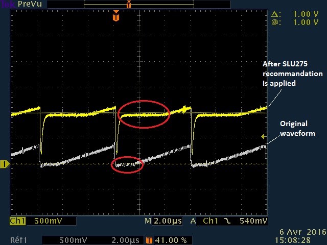
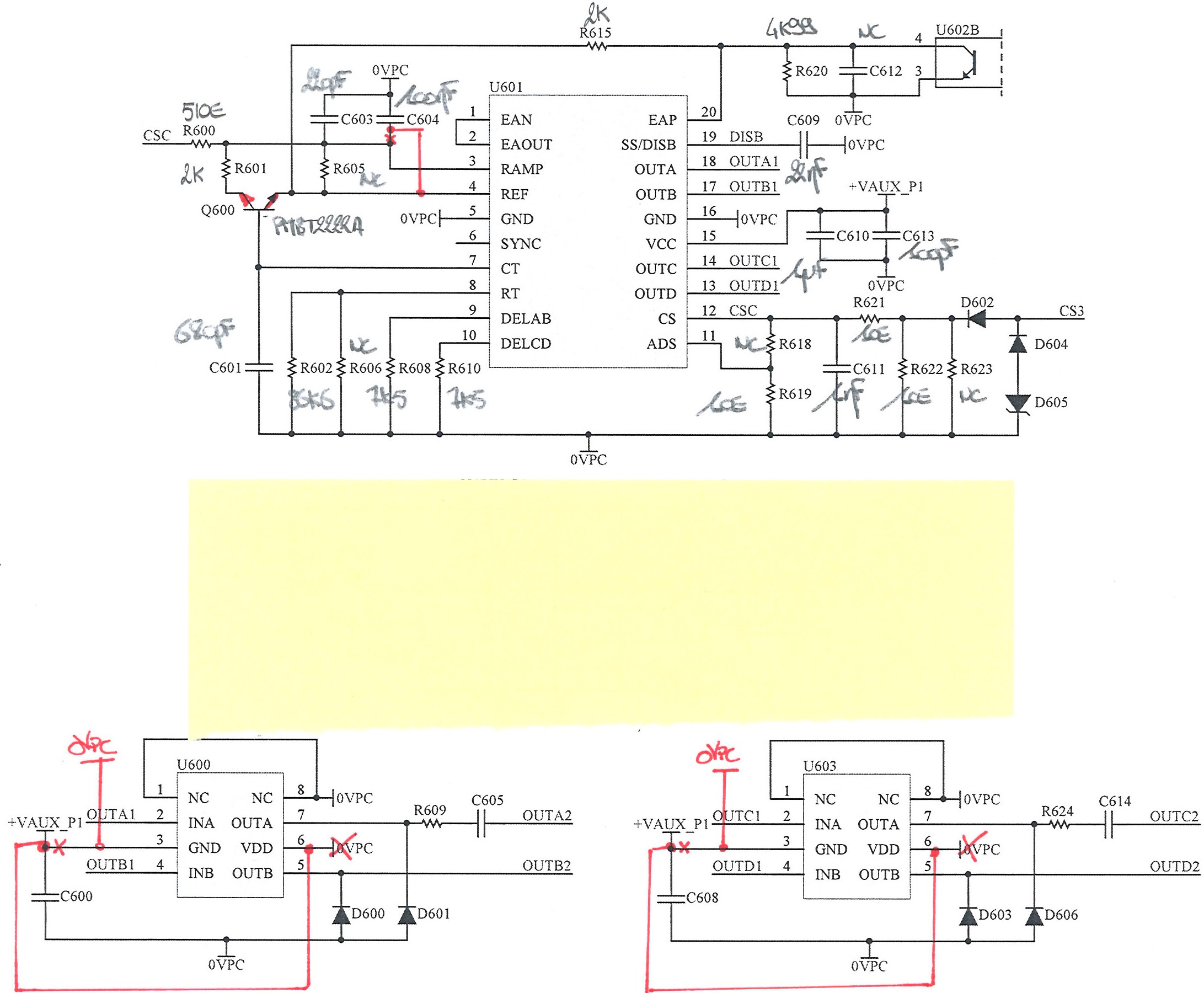
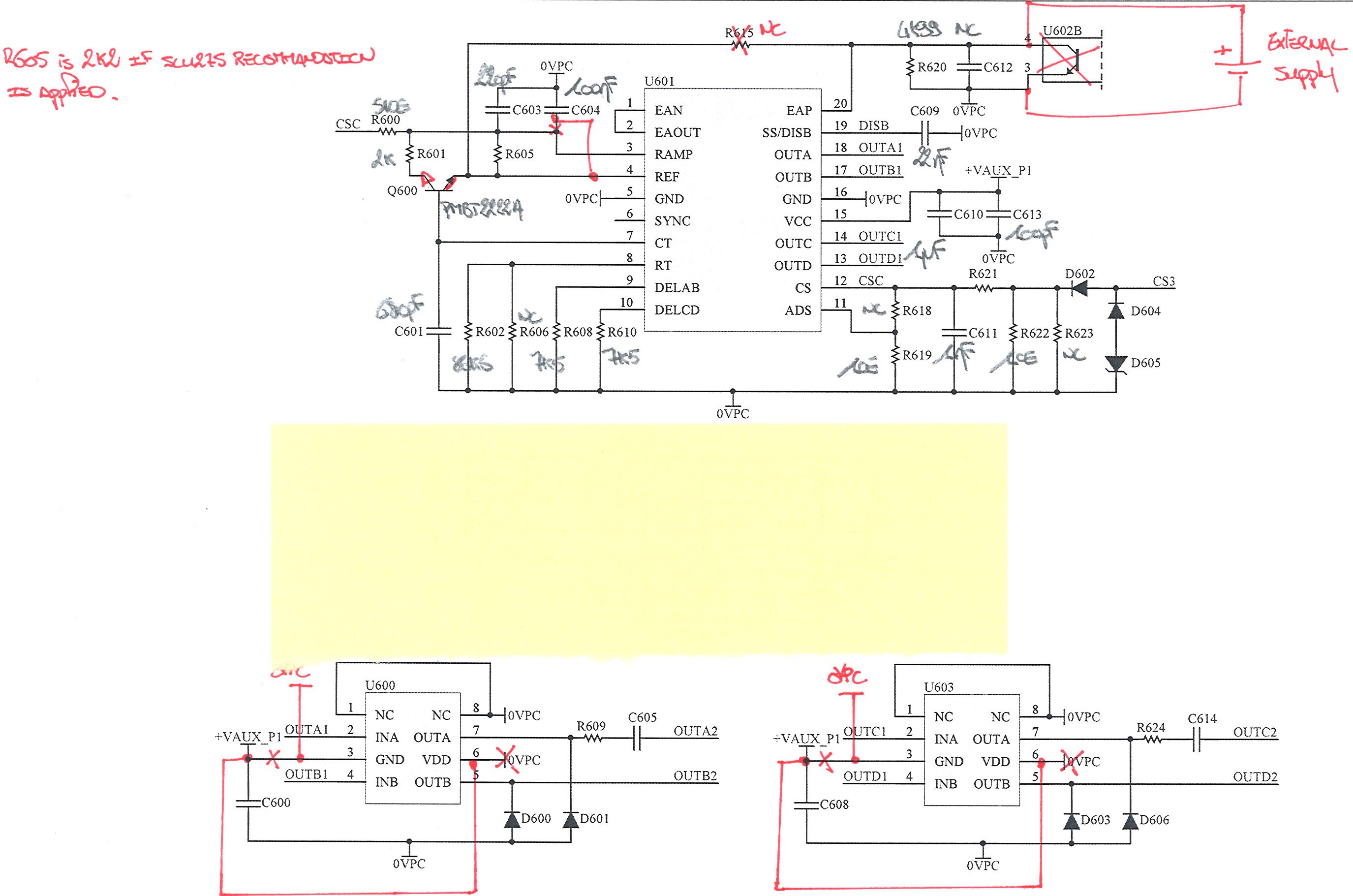
OUT C and OUT D are assymetrical when COMP is approx. 0.87V. As recommanded in SLU275, I have inserted a 1V DC offset to the ramp with a 2.2k resistor. The ramp now looks like what is shown in SLU275. Now, the operation is correct at 0.87V but the operation is assymetrical again when COMP is approx. 1.82V. Bascically, I have pushed the issue 1V above. Have you experienced a similar situation? (Normally pictures should be enclosed in this post).

PICTURES.zip

  • Hello again,

    To sum up the situation, I am in Peak Current Mode Control and I operate in open loop i.e. EAN=EAOUT and EAP is controlled with an external power supply.

    No 400V input but I only supply VCC to circuit and control EAP with an external power supply. OUT C and OUT D asymmetrical behavior occurs when COMP cross the lower part of the RAMP :

    - When SLU275 is applied (@COMP = approx. 1.82V)

    - When SLU275 isn't applied (@COMP = approx. 0.87V)

     I do not know if the flatness of this area can explain this behavior (see picture below).

    This situation is similar to a Voltage Mode Control with a low RAMP signal, isn't it? So I wouldn't expect this behavior.

    Assymetrical operation at COMP=0.87V.TIF

  • Hi Guillaume,

    We will take a look at this, do you have a schematic of the circuit around the controller that you can share?

    Regards

    Peter
  • I read the app note, SLUA275 and you seem to have implemented it correctly.

    I don't know how much slope compensation you have applied, normally one adds a ramp whose slope is 50% of the output inductor downslope and in this case I would suggest you increase the amount of slope compensation applied to the RAMP and CS inputs and see if the behaviour improves.

    There is also a possibility that noise is being injected on to the CS or RAMP inputs but I'd check the slope compensation first.

    Let me know how you get on.

    Regards

    Colin

  • Yes Peter. Please find two schematics below:

    1- Original schematic

    2- Schematic when testing with EAP tied to external supply