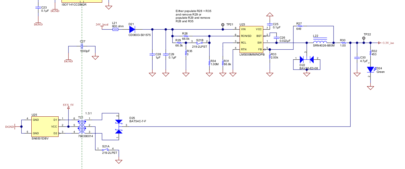
Can somebody explain the LM5009 step-down converter with SN6501 backup power supply as seen in TIDA-00183 to me?
- What is the intended use of R28, R29, R35 and S21B?
- Why are these values chosen for R_CL (R31) and L22? These values are outside of the recommended values as calculated from the datasheet.
- The output of the SN6501 isolated supply (U25, T21, D25) is unregulated and will probably drop by about 250 mV depending on load current. Load sharing is handled by 1 ohm resistor R30. As long as the voltage output of the LM5009 is a bit higher, I guess there are no issues. What is to be expected if the output of the LM5009 is lower? Are there issues to be expected with ~250 mA being fed back into the feedback node?
- How to assure that when 24V_local is present that the LM5009 is supplying most of the current?
I'm thinking of using a similar circuit, with increased output voltage of the LM5009 (5V or so) and then add a diode from TP22 to a +3.3V fixed LDO. Any tips/tricks/recommendations for such a circuit?
Thanks!