This thread has been locked.

If you have a related question, please click the "Ask a related question" button in the top right corner. The newly created question will be automatically linked to this question.

TPS92640 Current overshoot on first switching cycle.

Other Parts Discussed in Thread: TPS92640, LM3409

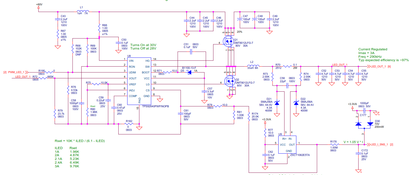
I'm using a TPS92640 for 60V to about 50V at 1A LED driver.

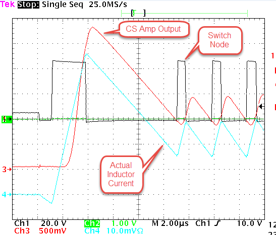
Using the UDIM pin to dim, and when it is enabled (UDIM goes high), the first High-side ON pulse is very long, causing the inductor current to go to about 2.5A peak. Then the low side turnes on, current comes down, and normal switching ensues around the target 1A average.

I have tried changing the COMP cap, no change.

Changed the inductor from 33uH to 47uH, and sure enough the peak current is lower. It seems that this first pulse just has a fixed, specific ON time.

During that first long pulse, the CT cap doesn't charge. On subsequent pulses I can see it charging during the ON time. Why is that? 

Changing the RT and/or CT value changes the frequency but it also changes the duration of that first long pulse.

What determines the first ON time after UVLO goes high (UDIM)?

Layout is clean, signal ground is isolated with a jumper around the controller IC.

Thank you.

  • Is there any way you could provide a schematic? I would also like to ask what you mean about signal ground isolated with a jumper? What is the PWM frequency and duty cycle you are seeing this at? Thanks.

  • How do i include an attachment?

  • After you hit "reply" click on "use rich formatting" to the bottom right. That allows attachments.
  • Here is the schematic. Notice that I'm using a current sense amp to move the current sense from high side to low side. This is because the customer's existing LED fixture uses a common ground for all of the LED strings, so I don't have a separate GND wire for each string.

    R182 is my connection from "quiet" ground to power ground.

    Also, for now, C61 is removed and R74 is shorted.

    I've also attached a scope shot:

    Cyan = inductor current (0.5A per division)

    Red = output of the current sense amp;

    Black = switch node.

    you can see that the first pulse is about 2.4usec long, causing inductor current to go up to 2.8A. After that, it discharges, then resumes normal switching around 1A average.

    The current sense amp may be contributing, but you can see that it responds very fast, it lags a little behind the actual inductor currrent, but it overshoots way past where the current should regulate. Once the current sense signal passes the set point, it is about 800nsec before that first pulse terminates.

    Thanks -

  • I can't say for sure if the current sense IC has anything to do with the issue or not, I am not familiar with it. But I do have some questions and concerns:

    1. How long is the LED current off for before you pull UDIM high again? If it is longer than 8ms you could be going into low power shutdown mode. I ask this because the low side switch turns on briefly causing the inductor current to go below zero. It could be that the boot cap needs to be recharged and that is doing something strange. I also noticed that the output voltage is very low by the time switching starts again.

    2. I can't see the layout, but I'm a little concerned about using R182 to tie the grounds together. I generally recommend a sold ground plane for everything. But my main concern in this case is that the CS ground is on the signal ground side. Its ground needs to be tied closely to power ground, particularly near the DAP connection and input capacitor grounds if possible. This obviously has a large voltage slew along with the current rising and that could easily cause an error between the power ground and signal grounds for a brief time and cause an overshoot until things even out.

    You should be able to solder thick wires to shore up the grounding and see if that gives you any improvement. It also wouldn't hurt to see if it works fine without the current sense IC. But on that note is there a reason you didn't consider the LM3409 for this design? It already has high side current sense so no external sensing IC would be necessary. It isn't synchronous, but at such a high output voltage relative to the input it would be about the same efficiency anyway.

  • I think you found the issue. Still verifying, but I didn't realize that the low power mode killed the internal Vcc rail. I changed the schottky diode to a std silicon switching diode, now it starts nicely. I'll post again later once I've verified that it is a good fix.
    On the isolated "quiet" ground, normally I agree with you. This is a busy board with four of these drivers, and a bunch of microprocessor stuff. When it's this busy I use the ground short and it always works well. Sometimes it's not really clear what returns to put on which side, but in that case (like the Vcc bypass cap for example), I just place that return point right next to the shunt so they are all within a few mm of each other.
  • It's something to do with the CS amp. It seems to have some delay on the first pulse, but once it gets going it seems plenty fast. I hacked in a low side resistor instead of the CS amp and it looks pretty good, very little overshoot on that first pulse. I'm going to play with it but I've also ordered some INA193s to try - they look like they have a faster slew rate on large steps. I'll update when I have something new but it may not be til late tomorrow.
  • Update - the CS amp causes a first-pulse overshoot due to its limited slew rate and some start-up latency. And I was allowing the PWM input to put the part into the low power mode, so I've fixed that.
    Comment on that low power mode: the part should NOT allow switching to start until the internal regulator has stabilized. Starting immediately from the low power mode causes out-of-control operation with high peak current and, in my case, FET destruction.
    And I also found that the OVP seems to not work at all. When it gets to the OVP threshold, for some reason it just starts switching very fast, like 1.5MHz or so. This also is destructive because of FET switching losses (I am running at 60V input). I had to set OVP above Vin, so it just runs up to a high duty cycle when the LEDs are disconnected, but at least it looks normal and the frequency doesn't go crazy. Comments on this OVP issue? I don't see any waveforms in the data sheet or in the eval board documentation, which is suspicious.
  • I was not involved with the development so I'm not as familiar with it as I could be, but I do know who tested it and I believe they would have caught a startup issue. Perhaps it has something to do with the external current sensing? Or perhaps you hit a sweet spot where VCC is near UVLO and the input voltage dip at turn on drops it briefly into UVLO and causes temporary loss of control? I am not sure, but I know I have not seen in on the bench in my limited time with the device.

    As for the OVP, it sounds like it could be a noise issue since there is not much hysteresis. Try adding a capacitor from VOUT to ground somewhere in the range of 0.01uF and 0.1uF. I would start with the lower value and increase until there is improvement. Of course it could be a layout issue as well, but we can look at that if capacitance doesn't help. But the output will not exceed the input so if you can tolerate that high of a voltage (basically if your output caps are rated high enough) then you can just disable OVP by grounding it and save the resistors.

  • And yes, this datasheet is a bit lacking. It's not for any suspicious reason, the writer just omitted some useful information.