This thread has been locked.

If you have a related question, please click the "Ask a related question" button in the top right corner. The newly created question will be automatically linked to this question.

TPS782 transition between current loads problem

Other Parts Discussed in Thread: TPS782, CC2640, CC2650, TLV713

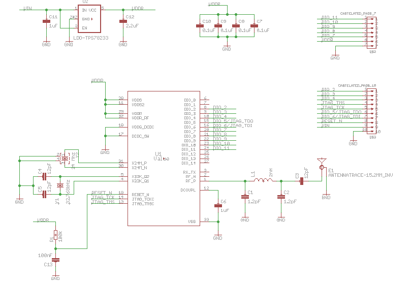
I made a module with the cc2640 powered with a external regulator (TPS782). As i explain in a previous post i was suffering strage behavoir when i tried to comunicate with the bluetooth. It results that the power output of the TPS782 was droping in the transitions from the low current load of the cc2640 in sleep mode, and the relative high current in communication mode made that the voltage drops below the minimun voltage of the cc2640 and it resets.

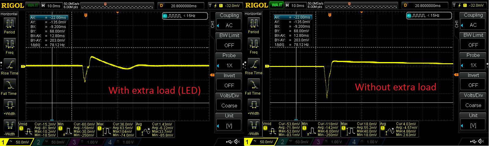
If i put some extra load on the output of the regulator it works ok. There are some grpahs of the output voltage of the regulator:

In the graph of the right the extra brusts after the first one are caused by the reset of the device.

I tried puting some extra capacity on the output but it didn't work until i used a 100uF electrolitic capacitor. The graphs with the extra capacitors:

This is not a solution, i need a better filter, and i have no experience in this field, could you sugest me a better solution?

Thanks.

  • Hi Juan,

    It looks like you are seeing the transient response of the LDO. Do you have an estimate of the normal load to light load transition (magnitude and slew rate)?

    TPS782 has an ESR requirement of less than 1ohm for stability. Are your existing capacitors ceramic? If not, please confirm that the ESR is less than 1 ohm.

    Would it be possible to provide an additional scope shot of Vin (dc), Vout (ac), and current?

    Very Respectfully,
    Ryan
  • Hi Ryan.

    I'm afraid i can't make the test until monday, but i'll try to give you the data from the TI documents.

    From the document of the power consumption of the cc2650 i get this graph:

    So the transition is from 500uA to 6mA (max). And i can't measure the slew rate from the graph, but in the cc2640 datasheet (page 21) it says:

    In the output of the LDO i use a ceramic capacitor:

    TAIYO YUDEN EMK107B7105KA-T  Ceramic capacitor multilayer, Serie M, 1 µF, ± 10%, X7R, 16 V, 0603

    Thanks for your help.

  • Hi Juan,

    Thanks, it appears that you are actually seeing multiple transient responses withing a short period of time. Increasing the load capacitor will help decrease the magnitude of the transient responses as you found; however, I am surprised that you had to jump to such a large capacitor.

    TPS782 is a low Iq LDO. As a result, the transient response is not as fast as some other LDOs. An LDO such as TLV713 has a faster transient response and would not require you to spin your board.

    Very Respectfully,
    Ryan
  • Hi Ryan,

    I made 3 boards and only two of them have this iseue, one of them works as is (thay are hand soldered, so maybe there are some fails). I'll do more boards and more tests and i'll buy some TLV713 as you sugest. But i'd like to use the TPS782 because the application for the module is ultralow power, so the less consum the best.

    Any idea why i need such a high capacity to smooth the transient?

    Thanks.
  • Hi Juan,

    Additional capacitance reduces the magnitude while slowing the transient response. Essentially what occurs is that the capacitor supplies the voltage when the LDO voltage drops (reduction in magnitude) and then the capacitor is charged by the LDO (increase in time).

    There is a trade off with transient response and Iq within LDOs. Additional Iq allows for a faster transient response.

    Very Respectfully,
    Ryan