This thread has been locked.

If you have a related question, please click the "Ask a related question" button in the top right corner. The newly created question will be automatically linked to this question.

BQ2970 Not recovering from Short circuit protection

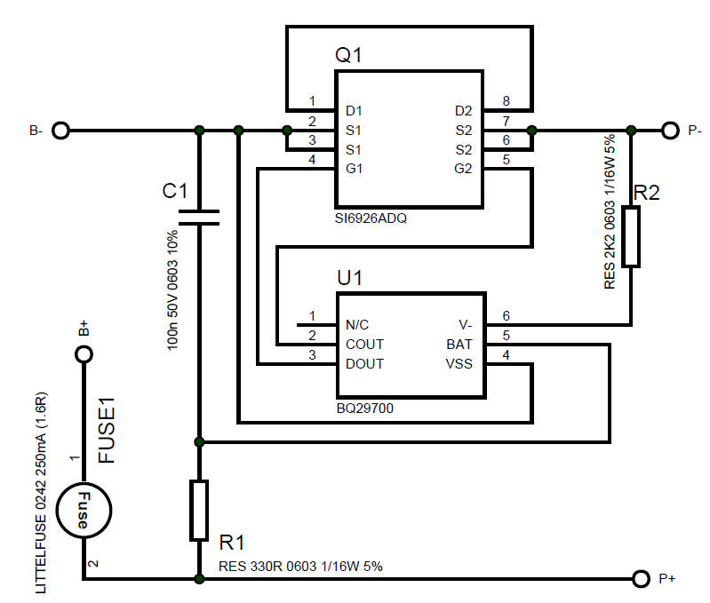
I'm having a problem with the BQ29700 IC.

When I first connect the battery, I need to insert the charger in order to properly enable the discharging circuit. I'm ok with that and the datasheet mentions this routine.

After that I can see the voltage between PACK+ and PACK- (3.57V).

I'm testing the short circuit protection, and once I tie "PACK+" to "PACK-" I can see that the DOUT is no longer HIGH and the P+/P- voltage drops to 0.20mV

Here's the problem, the BQ29700 is not recovering from the short circuit protection unless I insert the charger again.

After the short circuit the voltage between VBAT and VSS is 3.57V and the voltage between V- and VSS is 2.54V.
From the datasheet, the recovery will only happen when the diference between VBAT and V- is higher than 1V and even when this condition occur the IC can't release the protection state. 

When I put some load between "PACK+" and "PACK-", the voltage between PACK+ and PACK- rush up to VBAT level and quickly return to 0,20V. After that the voltage between P+ and P- became a sawtooth and adding the load just increase the frequency a little bit, but the voltage is never higher than 2V.

  • Alessandro Soncini said:

    Here's the problem, the BQ29700 is not recovering from the short circuit protection unless I insert the charger again.

    After the short circuit the voltage between VBAT and VSS is 3.57V and the voltage between V- and VSS is 2.54V.
    From the datasheet, the recovery will only happen when the diference between VBAT and V- is higher than 1V and even when this condition occur the IC can't release the protection state. 

    I believe this is normal operation.  Once the transistor turns off, it has no way of knowing if the over-current condition would persist if it turned the transistor back on.  
    I'll be interested to see if the experts at TI agree.  
  • Alessandro,

    You are correct in expecting the system to recover when you remove the short and V- returns to 2.54V, but the specification for VSSCR is TYPICAL 1V, meaning there is going to be some distribution around 1V.

    Are you using the 2.2k resistor or a different value? The current source that is connected between V- and VSS may be losing headroom and not continuing to pull charge off the V- pin to continue dropping the voltage.

    As Charles states, connecting the charger is normal operation.

    I'll look into available information on the distribution of VSSCR. Just for completeness, have your tried running this test with a higher battery voltage?

    Todd

  • Todd Vanyo said:

    Are you using the 2.2k resistor or a different value? The current source that is connected between V- and VSS may be losing headroom and not continuing to pull charge off the V- pin to continue dropping the voltage.

    As Charles states, connecting the charger is normal operation.

    Can you answer my tangentially-related question about the 2.2k resistor in an other thread?  Thanks!!

  • Thanks for your reply Charles.

    Well, the datasheet include information about releasing the short circuit state. "VSCCR Release of Short Circuit detection voltage"

    For this reason I think this is not the normal operation. It seems strange to me that after a sudden short circuit the user needs to plug the charger.

    I've tested a protection IC from Ricoh and it releases the state as soon as the short circuit is removed.

  • Thanks for your reply Todd.
    Here follows the schematic:

    SI6926 is Dual N-Channel Mosfet.
    The fuse has a cold resistance of 1.6R

    I thought the fuse could be the problem so I've repeated the test with and without the fuse and the problem happens either way.

    I also did what you suggested. I tested with a fully charged battery (4.06V - It'll not charge more than this because of the fuse cold resistance).
    The voltage between VSS and VBAT was 4.05V and the voltage between V- and VSS was 3.26V.

    I've tried putting some load on P+/P- but the V- voltage is always 3.26V.
    I've tried with 9R, 18R, 1K and 10K.
    I've waited about 1hour and the voltage was still 3.26V.

    I don't have a battery with a higher voltage, but I can make a 8V battery using 2 cells if you think I should repeat the test.

    I'm also assuming that this test could not be done using a linear power supply because of the battery impedance.

    Please let me know if need any waveform from the scope.

  • Hi Alessandro,

    I believe you can try to use a resistor as the "battery" and play with the voltage this way to make sure you can play around with the voltage.

    can you confirm if when you remove the "load" the V- pin goes to Vss (BAT/2) potential?

    Miguel