This thread has been locked.

If you have a related question, please click the "Ask a related question" button in the top right corner. The newly created question will be automatically linked to this question.

TPS61070 at light load and high Vin: have a problem (burns out)

Other Parts Discussed in Thread: TPS61070

Hi there!

I use the power supply based on the TPS61070. Normally it converts 3V to 5V @ load current from 1 to 30 mA. In this case I have no problem at all. When I need to switch input voltage from internal battery to external source ( USB ), I simply connect it to 61070's input through a diode, so, its input voltage becomes about 4.3V.  If the load current stay the same, all works properly. Otherwise, when I reduce load current (a newer controller in sleep mode comsumes only several uA), after several time which depends on the used USB port, cable etc, my power supply burns out. The 61070's SW pin have about 4Ohm to GND. 

Tell me please, what happens? I didn't find any info in datasheet. All absolute maximum parameters are respected. Is there some techniques to protect the IC from this trouble? Thanks in advance.

Vsevolod.

  • from your schematic, the inductor is15uH, could you change it to 4.7uH as in datasheet. high inductance could cause stability problem.

    the two output capacitor, C13, C14 is ceramic capacitor 10uF, correct?

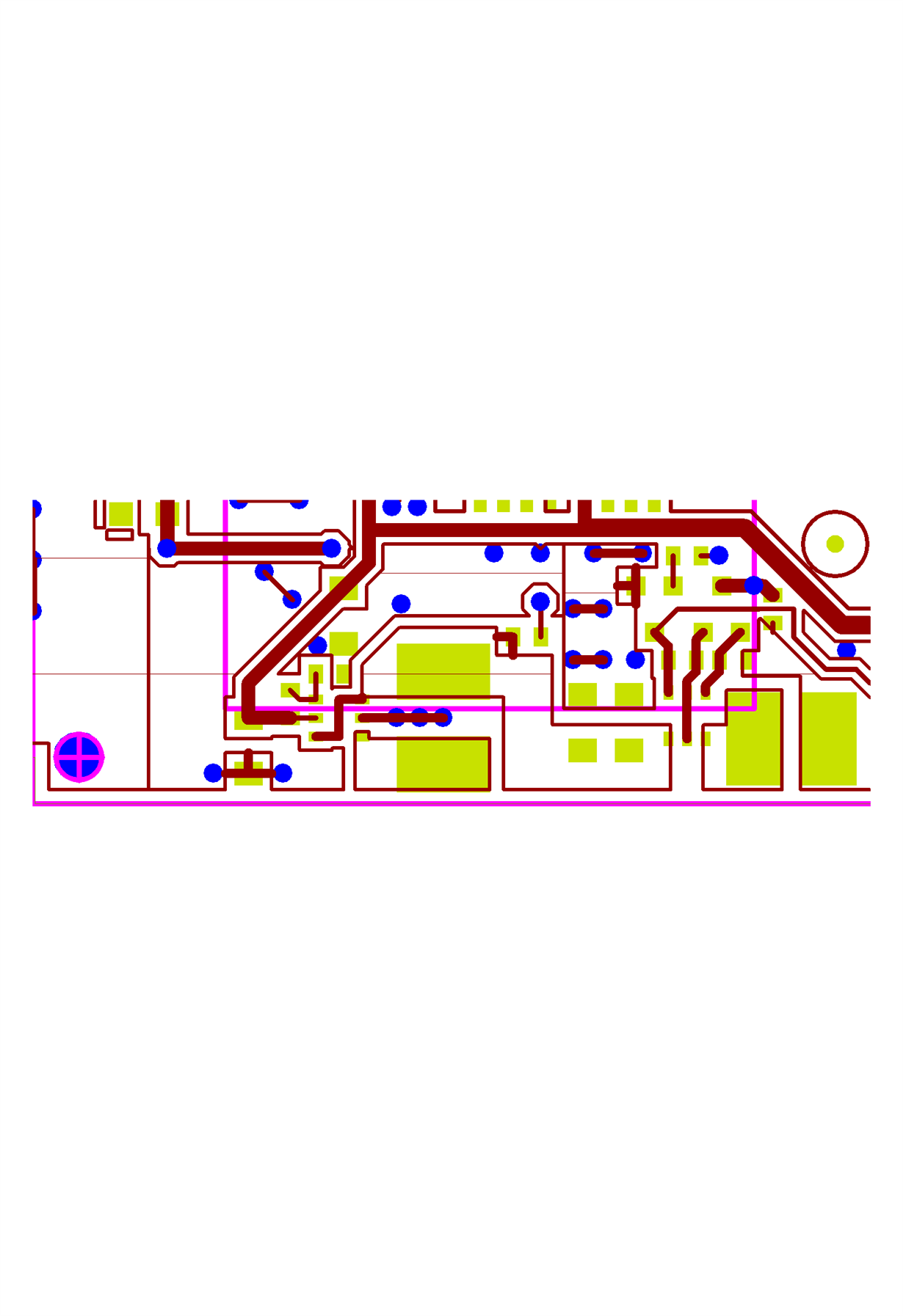
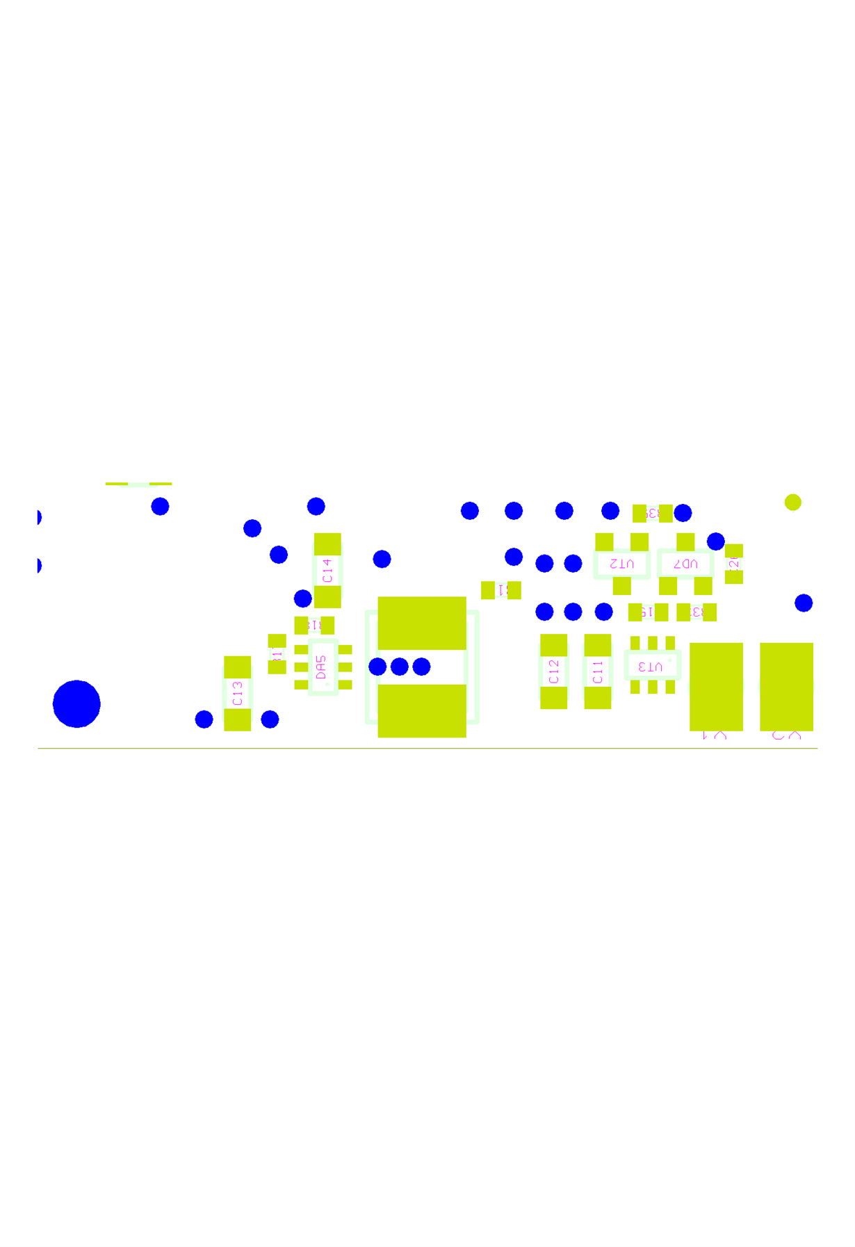
    please also share your layout, damage problem could happen with bad layout.
  • Thank you for a reply, Jasper.

    All capacitances are ceramic, right. In some datasheets is written about stability limits. I saw no such info in 61070's this one. Is this information available at all?  What about layout: all traces are as short as possible, I use polygons and ground plane.

  • one problem in your layout is that the GND pin of the IC and COUT is connected through the VIAS. So there is risk that high voltage spike in SW pin could damage the IC. please place a ceramic capacitor above the IC and connect the cap to the IC's VOUT and GND pin with solder.


    please also change the inductor to 4.7uH to check if the problem is solved.

    about the stability, if you following the datasheet to select the COUT , inductor and feedback resistor. the stability would not be a problem.

  • 3 vias in parallel - it's really not enough? Many times I used the similar layout, but have a problem only right now. However, I'll avoid it in all next designs, thanks. I already ordered new inductors (Murata LQH3NPN4R7NG0L) and hope to get them in 1-2 days. I'll follow your recommendation and then reply about results.

    Thank you again.

  • I'm sorry, but all your suggestions was useless. I placed a short and thick wire directly from 61070's GND pin to the nearest capacitor's GND. Of course, the inductor also was replaced with this one I already mentioned (4.7 uH). As earlier, 61070 and next diode VD7 have been burnt during 1 minute after connection at USB 3.0. As I guess, USB 3.0 can supply up to 900 mA, so it become fatal for IC.

  • it seem the damage is caused by something not just related to our device.
    could you measure the waveform of VIN, VOUT, SW and inductor current (connect a line in series with the inductor, then measure the current flowing through the line) during this 1min period. observer if there is abnormal input voltage, output voltage or very high inductor current.