This thread has been locked.

If you have a related question, please click the "Ask a related question" button in the top right corner. The newly created question will be automatically linked to this question.

BQ24650 Problem - failure on BTST pin?

Other Parts Discussed in Thread: BQ24650

Hi TI Community,

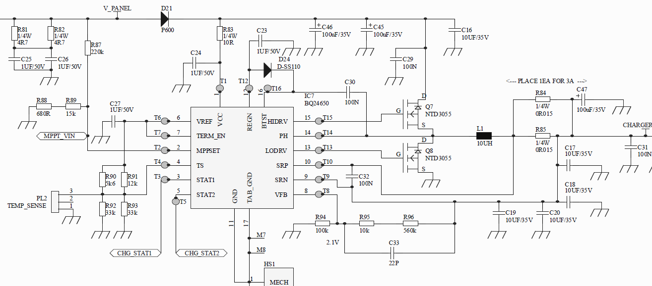
OK, I have been testing with a solar charger circuit using the BQ24650 part, into a "12V" lead acid battery. The solar panel has a MPPT voltage of approx 18V, and an OC voltage of approx 23V, the panel is rated as "50W", so approx 2.8A input for maximum sun. I have set the voltage output via feedback resistors to 14V, and the SRP/SRN current sense resistor to 0R015, in the 3A region.

My circuit and PCB follow Fig 1 of the BQ24650 datasheet fairly closely, except for MPPSET, VFB, and TS resistors changing for my design. Power FETs are 2X NTD3055 parts- perhaps not the best for efficiency, but good enough to get testing.

Since I am testing at night, I am simulating the solar panel with a bench supply, set to 22V and 3A current limit. When operating properly, the circuit pulls the bench supply (in current limit) down to 18.2V. So, MPPT functionality looks good.

The problem I have is this: for a few hours of testing, the circuit behaves as expected (OK, the power FETs get rather warm!). However, it then stops charging and never starts again - even after the supply and battery being disconnected, to reset any internal timers.

The output (battery) voltage is below regulation, so it should charge. The TS input is "mid band" for operation (I have even used a potentiometer to set the voltage accurately to mid band, so as to rule this out).

I have gone through the list of "ENABLE AND DISABLE CHARGING" in the datasheet, top of page 14. In normal working conditions, all of these are true. When not working, only one of these things fails: REGN is 0V. NB VREF is still 3V3.

When I replace the BQ24650 part, everything works again and REGN is >6V. I assumed my hand soldering of the part was the problem. But after an hour or so of testing with a part put down by my SMD contractor, the part stops working again. V_REGN is 0V. Unpowered, I measured from REGN to GND, approx 12ohms. By measureing around the part, I am fairlt certain that this low resistance is due to the BQ24650 part, not the circuit around it.

* Has the BQ24650 failed? No amount of trying on my part can get the circuit to start again, or for V_REGN to return to 6V odd.

* Am I over-stressing the part in some way? I notice in SLUU444A and SLVA437A that a 2R2 resistor is in series with the REGN pin: is this needed as some current limit?

* REGN feeds to BTST via a diode, and as I understand, as positive supply for the top FET driver. But by the datasheet, BTST is good for 34V, somewhat above my panel spec - why can I not diode OR BTST with the panel voltage and switcher feedback via 100N?

Any help/insight would be appreciated.

  • Hi Thomas,

    Do you have a schematic? I want to see all the cap voltage ratings as well.

    See if you can send a scope capture of LODRV, HIDRV and PH. If you can, include BTST as well.

    Also the FET you use have low drain current ratings compared to the ones used in the EVM. Is there a reason that you want to use higher Rdson?

    You need REGN as the reference voltage because you actually want VGS of HSFet to be around 6V, or gate voltage higher than PH voltage by 6V. We do this by using the bootstrap capacitor, REGN and diode. This is the case for many switching converters.

    Thanks,
    Steven
  • Hi Steven,

    Thanks for your interest. Please see a screenshot of my circuit below:

    NB: 100N caps are 50V.

    I don't currently have 'scope pics' for LODRV, HIDRV, PH and BTST, as my current development board is not working. But when the circuit was working, they were very similar to those shown in the datasheet. Generally, clean and square, LODRV at +6V, and HIDRV at +6V above PH (as best as my memory serves me).

    Yes, the power FETs on my dev board are not the best available, but readily available at short notice, and "good enough" to try out this circuit.

    I understand why BTST is needed, to turn on the high side FET. But you will will notice there is no series "2R2" resistor in line with BTST in my circuit, copied from the datasheet, but I notice many Application Note circuits contain this series resistor.

    Also, I've found that REGN is 'damaged' (0V output) when the circuit does not operate.

    So, I guess my question is: "is a 2R2 series resistor NEEDED inline with  BTST"? I have damaged 2X BQ24650 in the above circuit, is a series resistor needed?

    I am arranging with my SMD contractor to replace the BQ24650 part, thereafter I will "cut and wire" a 2R2 resistor in series with the BTST pin, and continue testing.

    thomasp

  • Thomas,

    The series resistor on the bootstrap capacitor is to limit the current going to HIDRV, hence reducing the ringing and noise on the HIDRV trace. This may improve ringing on the PH waveform as well.

    I suggest finding better FETs with less Rdson, find some similar to the EVM just to be sure.

    I cannot see the schematic, it didn't upload correctly.

    What is the end application of your system? Do you have information about the volume on this application?
     
    Regards,
    Steven

  • Hi Steven,


    I'll try the schematic image again:

    OK, it is shown in the Reply Editor...

    Thanks for your explaination wrt limiting current to HIDRV, but could it also be to protect the BTST output?

    Thanks,

    Thomas

  • Hi Steven,

    OK, it seems the circuit image has loaded.

    WRT application, I am designing a charger, from a 50W solar panel (Voc=24V, Vmppt=18V, 50W full sun capacity) to a 20-40Ah 12V lead acid battery.

    When complete/proven, I expect reasonable volume production numbers, but to be honest, we're still in concept phase, and still looking carefully at costing.

    Thanks,
    Thomas
  • Thomas,

    You should take a look at this app note, which explains how to properly modify the bq24650 schematic to charge a lead acid battery.
    www.ti.com/.../slva437a.pdf

    Regards,
    Steven
  • Hi Steven,

    I have been testing a modified version of this circuit, which included a 4R7 resistor in series with the BTST pin (I know the app notes say 2R2, but I had 4R7 available).

    I can confirm that after some amount of testing, there has been no failure with this circuit.

    @TI: please consider updating the BQ24650 datasheet, to include this resistor, as it is currently only shown in app notes and the dev board.

    thomasp
  • Thomas,

    Thanks for the update and glad that fixed your problem. I will take note of this.

    Regards,
    Steven
  • hi thomas i suffered a lot from the same issue u had , but the case i had is slightly different i noticed that as long as the battery and and solar input are connected and not removed and plugged again things goes fine , once i started to remove any of this after few times the bq24650 fails and doesn't charge any more i can see the data of this post around the end of April, do u still believe that the 2,2 resistance connected to the btst solved the problem , because aim going to do the same!!!? please reply me ,,,, one more thing do u thing that regular bench power supply can work instead of solar panel or i must use a solar panel simulator power supply ,,, thank you
  • Hi Ahmed,

    To simulate a solar panel, you need to add a series resistor to the output of the power supply.

    For Thomas this worked. Adding the 2R2 resistor at BTST pin will limit the amount of current passing through, which can diminish the current overshoot going into the pin and not damage it.

    Regards,
    Steven
  • Hi Ahmed,

    (Also responding to Steven's first reply)

    1) It seems to be very important to add a small series resistor to the BTST line; app notes say 2R2, I used a 4R7, as I had one handy, (1206 foorprint) which worked for me. Yes, it also worked after multiple connects and disconnects of the panel and battery, but I can't say if this (normal?!) operation caused the failure before I added a 4R7.
    Its quite expectable, the BTST input probably has some rectification (diodes?) and a small up-converter, to create the 6V greater than Vpanel to turn on the top FET. A very high dV/dt on this input could cause the device to fail. It happened to me on several PCBs...

    2) WRT simulating a panel, you can use a series resistor as Steven mentions. I found it easier to use a bench supply with a current limit, as follows:
    a) Set the supply Vout to the open circuit voltage of your panel.
    b) Set the current limit to the max current (or some lower value while you are testing), such that the product I x V of the current limit and MPPT voltage, equates to the panel power.
    c) When the MPPT charger loads the supply (or panel), the open circuit voltage will fall to the MPPT voltage, and regulate there. This is the "constant current" area you see in the datasheet.
    d) When the battery is fairly charged, the charger will enter constant voltage mode, and the current will slowly fall.
    e) This all assumes that the current feedback resistors set a max current ABOVE the expected max current of your panel - I'd aim for 20-30% above.

    I hope this helps,
    thomasp