This thread has been locked.

If you have a related question, please click the "Ask a related question" button in the top right corner. The newly created question will be automatically linked to this question.

Current Offset Error When Charger is Enabled in BQ40Z60

Other Parts Discussed in Thread: BQ40Z60

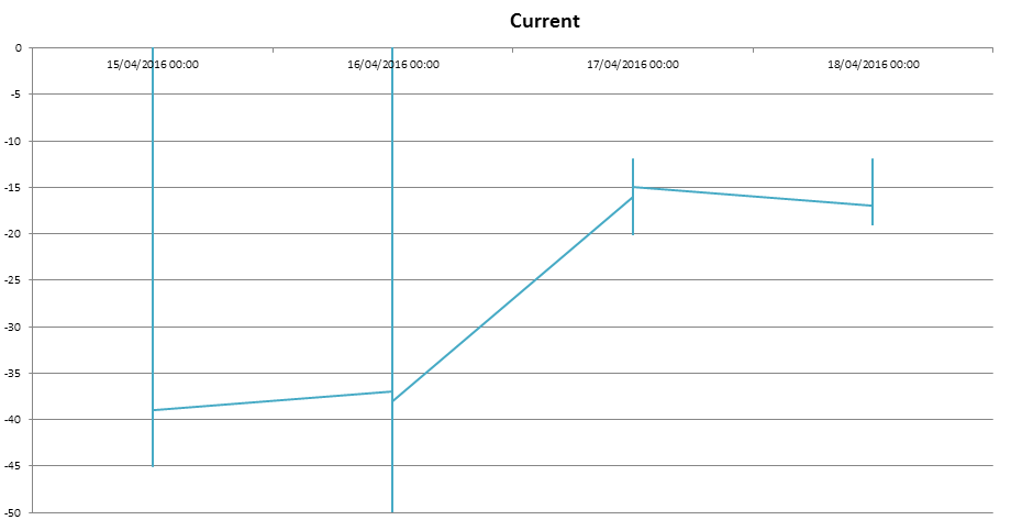
Last weekend, I left our board that uses the BQ40Z60 under these conditions: load to 550 mA on a regulated output set to 12V; charger enabled with 20V of input voltage; charged batteries. As you can see from the attached graphs, the gauge measuring always a negative current, although the batteries are charging. If I disable the charger and fets, the measured current is properly 0 mA. Is there a way to solve this problem? How much this error may affect the results of the gauge?
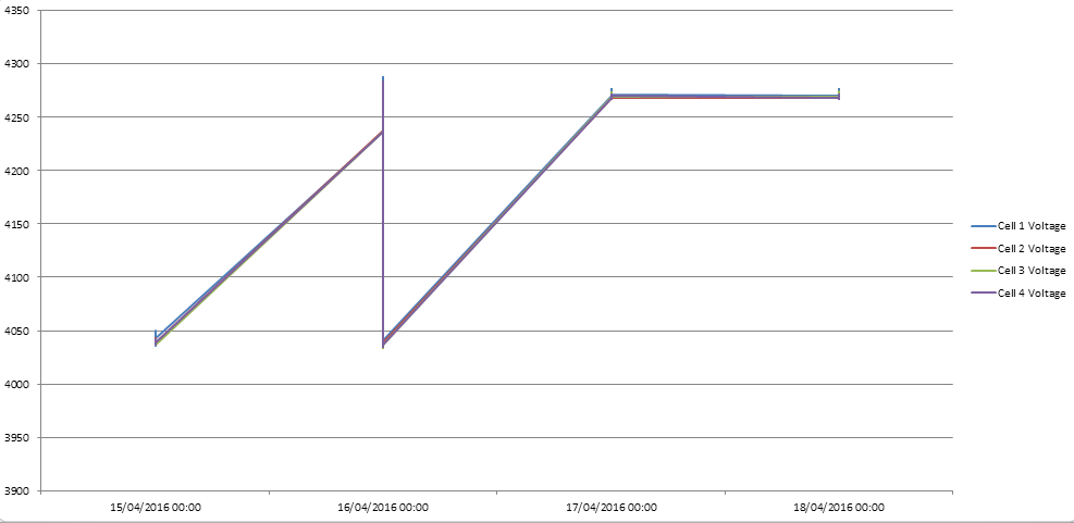
  • Have you tried monitoring the current while discharging without the charger enabled and charging without the load attached? If you have a load attached while charging, then current will go from the charger to the load first and this current does not flow through the sense resistor. If the charger cannot supply enough current, then current will be drawn from the batteries and this current is reported by the sense resistor. If the current is reported properly when only charging and discharging, then it should not affect gauging.
  • The charger can supply the charging current, that is more than two times the load current. When batteries are low, It charges it correctly.  Only when, battery are full, it measure a negative current. Also the discharge works. And, as you can see from figure, it measures negative current, but battery voltage continues to increase! So, it must be a positive current. I can also measure a positive voltage on the sense resistor.

    Waiting from you

  • Pietro,
    This must be a layout issue. If the gauge is reporting a discharge current, when there is actually current flowing in the charge direction, then an offset must have been introduced to one side of the sense resistor. This can cause a false charge or discharge current. Are the sense resistor and filter components located near to the bq40z60 devices? We should also review how the ground connections are made. Are the sense resistor sense traces truly kelvin contacts to the sense resistor?
    Tom
  • Can you please tell me your email, so I send you gerber for a fast check? Sense resistor and filter components are very close to the chip and Kelvin Contacts are used!

    thank you in advance