This thread has been locked.

If you have a related question, please click the "Ask a related question" button in the top right corner. The newly created question will be automatically linked to this question.

Having issues with TPS54540. Heat when under load.

Other Parts Discussed in Thread: TPS54540

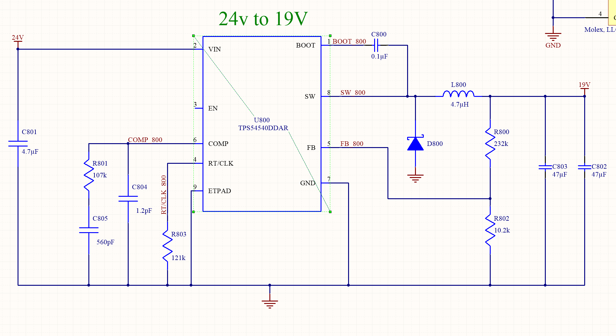
I recently brought in the TPS54540 to one of our boards. I am using 3 of them on 3 different power rails. The input for all of them is 24V. 

Power Rail 1: 19V @ 810 MHz

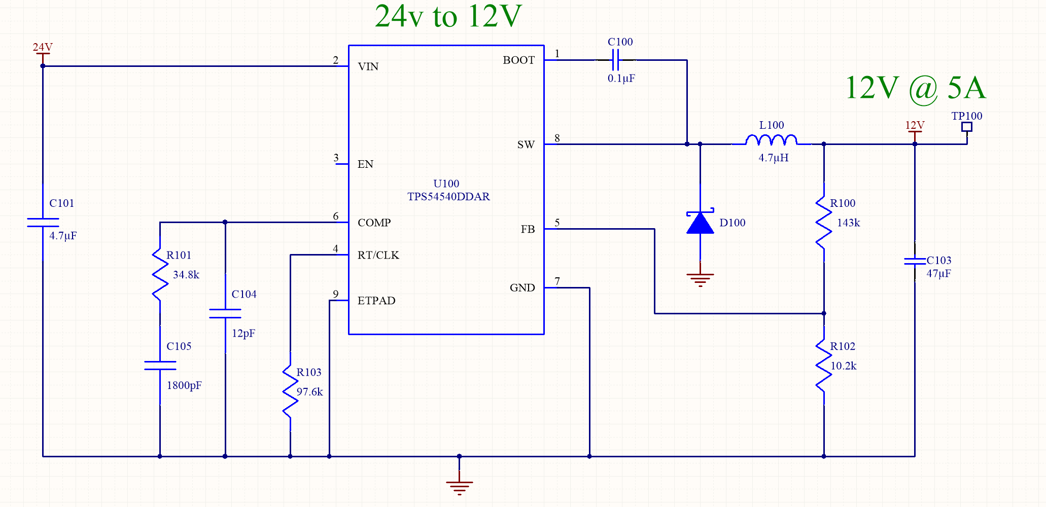
Power Rail 2: 12V, 1A @ 1MHz

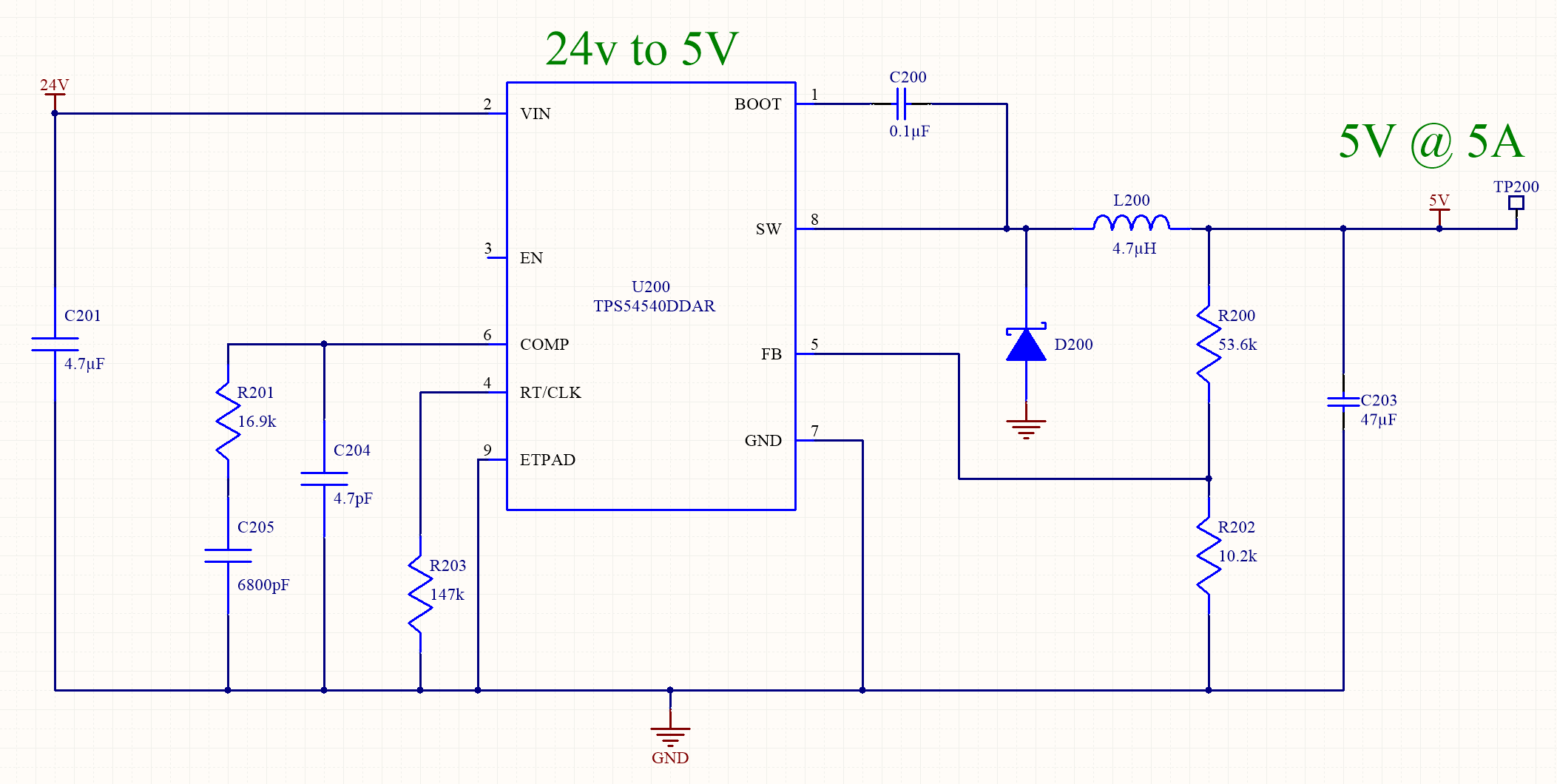
Power Rail #3 5V, 5A @ 666KHz

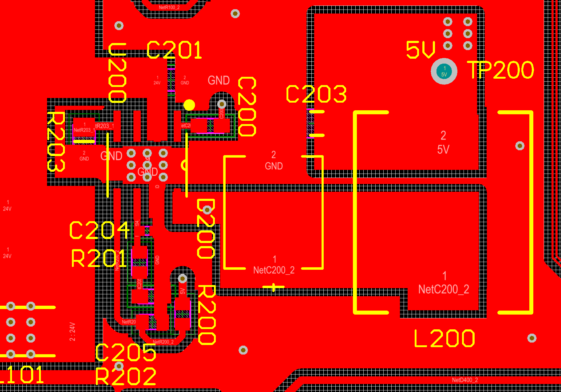
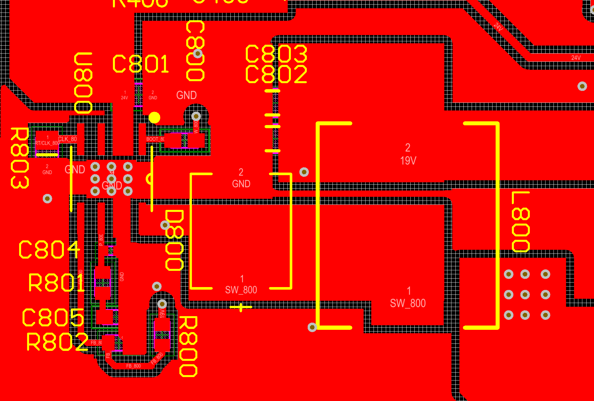
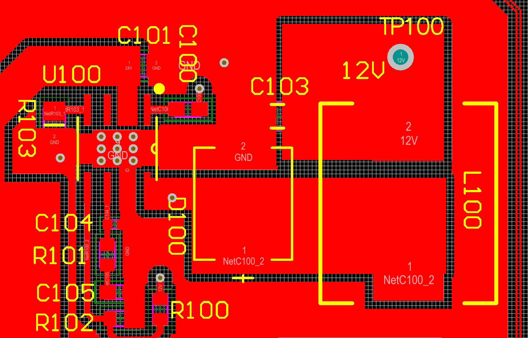
All the layouts are basic carbon copy of eachother, so if one is wrong, I am guessing they are all wrong. 

I used TI's webtool to design the circuits and validate the temperature performance. And it seemed to be OK. 

Problems: 

The 12V rail cannot output more than 1A before it becomes unstable and starts to shut down. 

The 5V rail cannot output more than 3A before going into shut-down mode (I am assuming thermal shutdown). 

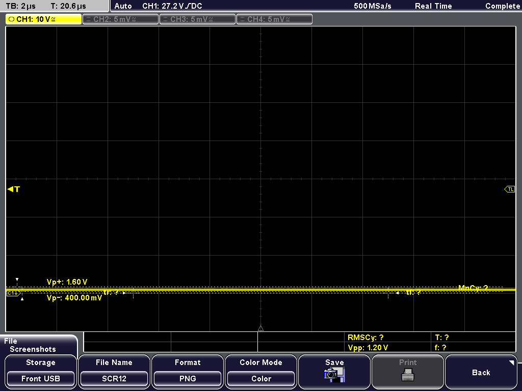
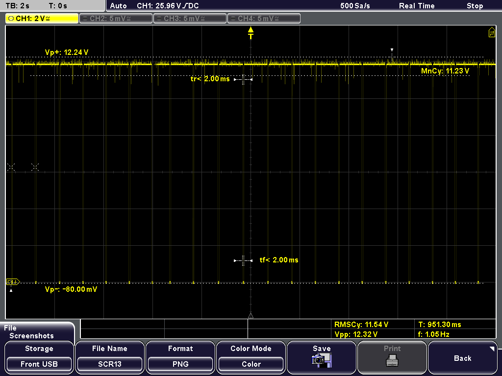
The 19V rail cannot output more than 1.5A before going into shutdown mode. 

Lay 2 is full copper ground pour. 

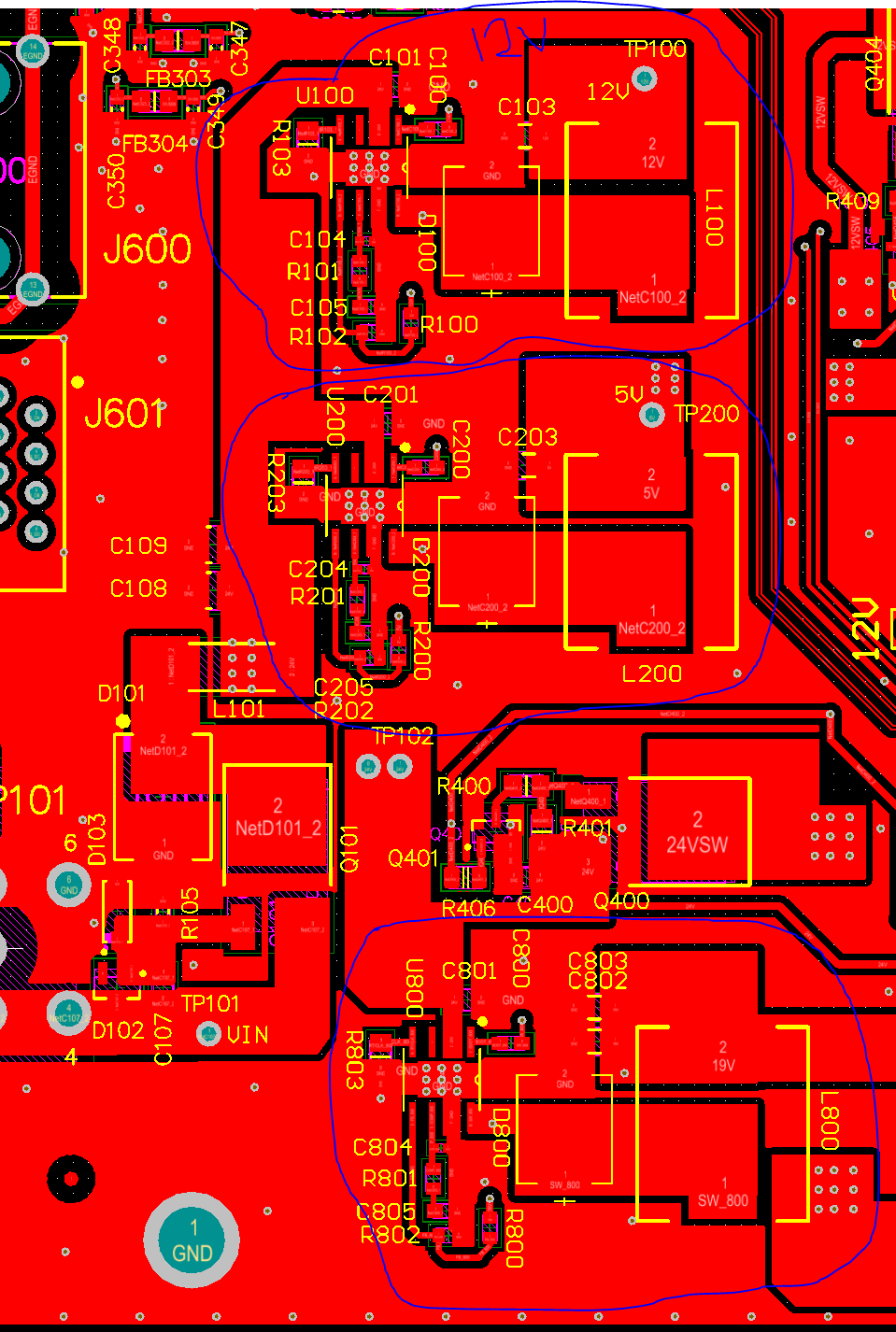
This is the location of all the DC/DC Converters

The Shottky is a B540C-13-F

Any help is appreciated. 

  • The layouts seem reasonable to me. I see the inductors are all the same values. That is somewhat unusual. Can you send me your webench designs? You can share them inside webench to j-tucker(at)ti.com.

    For your 12 V output you claim it is not stable. can I see the SW node. Vout and COMP waveform?

    The other 2 rails you suspect thermal issues. That should be easy enough to verify. Are the ICs getting hot? Are the exposed pads well soldered to the PCB?
  • Hi John,

    I see the inductors are all the same values. That is somewhat unusual. Can you send me your webench designs? You can share them inside webench to j-tucker(at)ti.com.


    I tweaked the webench design to make the inductors be the same size, I had to increase the frequency for the 12V and 19V rail. I will send the design files to that email. 

    For your 12 V output you claim it is not stable. can I see the SW node. Vout and COMP waveform?

    See images:

    Vout (minimal load):

    SW (minimal load):


    COMP (minimal load):

    Vout (0.5A load):

    SW (0.5A load):

    COMP (0.5A load):

    Vout (1A Load):

    SW (1A load):

    COMP (1A Load):

    Vout becomes unstable after a couple of minutes of 1A load:

    Regarding heat:

    I've measured up to 220F on certain portions of the PCB, but have been unable to trace down the source of the heat. Some very strange things have been happening. 

    While load testing the 5V rail with 1A of current, I noticed that the 12V rail was generating a lot of heat. This didn't make much sense to me, but I decided to completely de-populated the rail, and I can still measure a lot of heat coming from the section of the PCB from where the 12V rail is/was located. 

    This is a 4 layer board, and the plane beneath the top layer is a full copper GND plane. 

  • I would also like to add that there is a major efficiency problem.

    Vin: 24V
    Iin: 1A
    Vout: 12V
    Iout: 1A

    That's 24W in to produce 12W out. 50% efficiency. The other 12W are being dissipated as heat, no wonder the board is getting super hot.
  • A little bit more info:

    The heat is being generated by the 5V rail (on the board with the depopulated 12V rail). The Shottky is getting very hot indeed, so is the TI controller. But I'm only testing at 1A load, when it is supposed to work up to 5A.

    Efficiency is the main problem here. I need 13W IN, to produce 5W out. There are a total of 8W being dissipated as heat on the 5V rail.

    Any ideas why the efficiency is so low?
  • I found the source of the heat problem;

    The assembler made a mistake during the mounting. They mounted a TVS diode in place of the Shottky. Once I mounted the right shottky diode the DC/DC converters were operating at a reasonable efficienty.

    The 19V rail has issues operating at the top end of it's load capacity (3A). I hear a noticeable "Switching" sound.

    Can you provide any advice on the tuning of the 19V rail?
  • You sent me the WB link for the 12 V and 5 V. Can you send the 19V as well?
  • I can't seem to get webench to land on the same values as I have at 810KHz.
  • Yes the webench design you sent is totally different from the schematic you posted previously. I can make a comment anyway. If you notice, the compensation values are noticeably different from the 5 V and 12 V designs. The Rcomp value is very high at 107k and the Czero and Cpole values are very low. I find that suspicious.