There are a lot of boost converters among TI products.
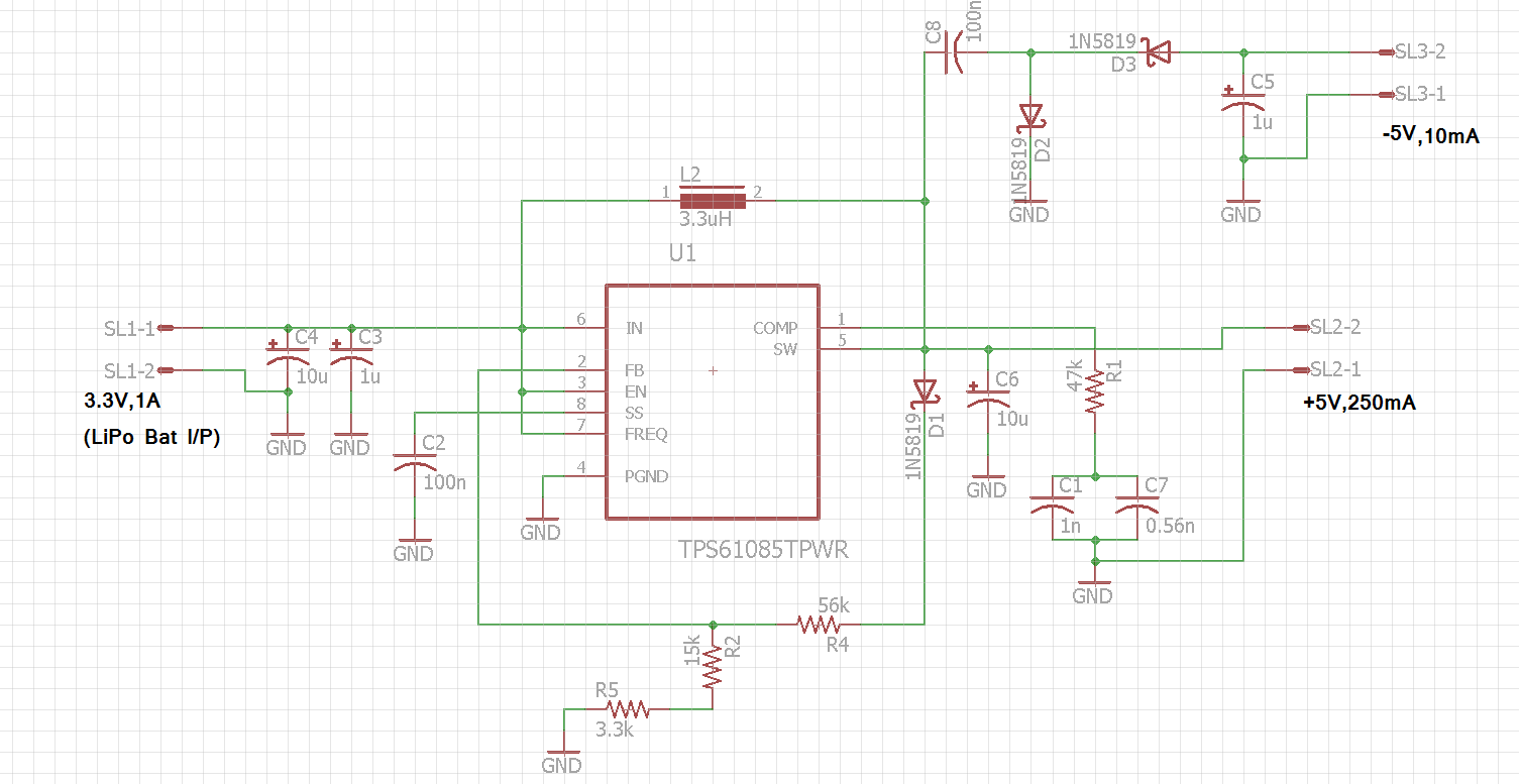
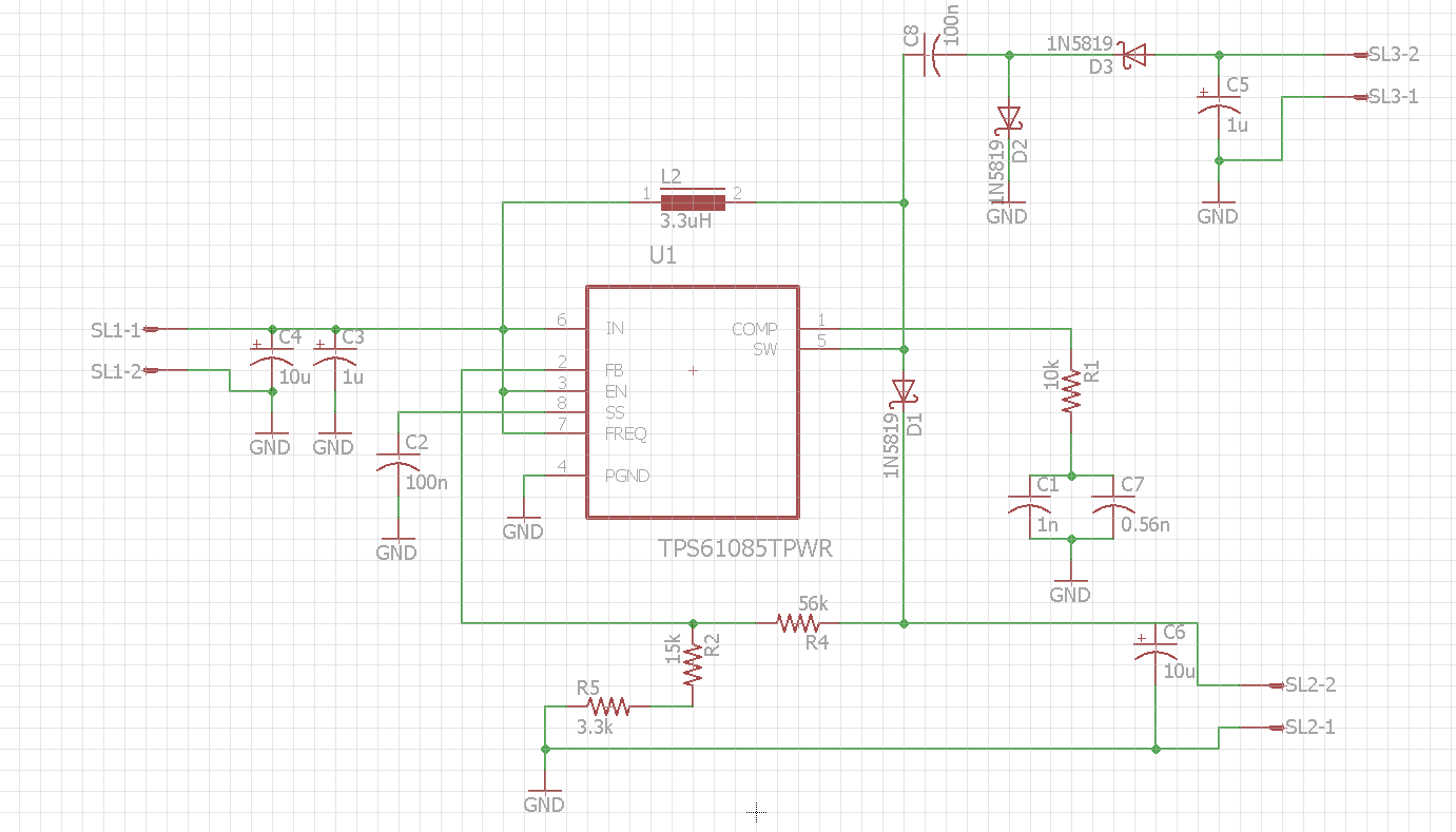
Can we use a boost converter to produce negtive output?
For example,the input is 3V,the expected output is -5V. Would you please give me the reference design?
Thanks!
This thread has been locked.
If you have a related question, please click the "Ask a related question" button in the top right corner. The newly created question will be automatically linked to this question.
What is the -5V output accuracy ?
You can refer to the TI design PMP9770. Get -5V by a negative charge pump.
What is the -5V output current? so that I can evaluate the possibility of the charge pump solution.
I think the voltage accuracy can be assured by zener diode if the precision requirement is not so high.
Is there any positive output for this Boost converter?
The desired -5V output current is 100mA.Is it possible?
If using the TI design PM9770,what's the maximum output current by the charger pump?
What factors influent the output voltage accuracy when using charger pump?
How to get lower ripple?
When the load changes, the output voltage will change a little. So is 100mA a stable load? Or it is a maximum load?
Hi Helen,
100mA is maximum load? Can we get it from the charger pump?
At the same time,we expect to get lower ripple,what methods can we
use it?
Vin(Lipo,1000mAh) | 3.3V | 1A |
Vout(-ve) | -5V | 10mA |
Vout(+ve) | +5V | <250mA |
Hi there,
I wanted to use TPS61085 in my power supply circuit, with input/output voltage requirements in table above. Main consideration is the current output.
I will use it to power a opamp circuit(+-2.5V @ 10mA) and wifi module(requiring more than 250mA current at 3.3V).
Op-Amp is OPA320.
Output + -5V or + - 2.5V? there are different values in the description.
The schematic is OK, only one point:
For the compensation network , if you choose Rcomp=10k, Ccomp=1.5-2.2nF(suggest you use 2.2nF), then the effective output capacitance should be >=10uF, I found you only add 1pcs 10uF cap at the +5V output side, the effective capacitance is not enough, please use at least 2pcs 10uF ceramic cap at the output side. if the package is very small, may need more. you need to check the ceramic cap datasheet to get it.
Hi,
Getting the required output of +5 volts and -5 volts. But the current output is very less about 50 - 80 mAmps.
I need more than 250mAmps.
Please tell the factors controlling the output current.
I have chosen:-
Rcomp:- 10k, Ccomp:-2.2nF(Ceramic), Cout:-22uF, L:- 3.3uH,
For charge pump circuit Capacitor Values are:- C8=1uF(Electrolytic), C5=4.7uF(Electrolytic).
Once again I repeat the requirements:
Vin(Lipo,1000mAh) | 3.3V | 1A |
Vout(-ve) | -5V | |
Vout(+ve) | +5V | <250mA |
Output current should be more than 250mAmps @+ 5volt output.
i'm wondering the efficiency is very low which cause the problem. Or your input wire is very thin and long which leads to a big voltage drop on the trace.
could you please share the detailed application information with us? Like in what kind of equipment? Volume? Which company? You can send the information to me by email, my email address is helen-chen@ti.com