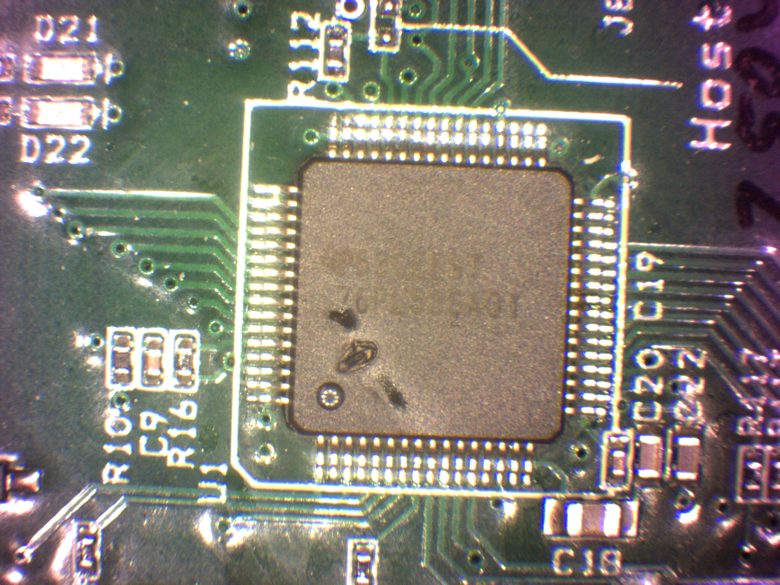
We've had a number of instances where our customer has damaged our prototype bq76PL536a BMS boards with an over-current event. The reference design EVM includes a 0.5W, 30-V Zener clamp diode on pack V+, which also connects to the chip Vbat1 and Vbat2 pins. When the failure has occurred, both the bq76PL536a chip and the Zener are visibly damaged (photo of the chip below). Seems prudent to insert some value of resistance between the pack V+ and the Zener/chip to give some hope of surviving this. Since the chip can draw 20mA or so normally, was thinking maybe a 20-ohm resistor. This will cause a pack voltage measurement error but that would be tolerable if survival improved from the anomalous event.
Question: would having the chip Vbat voltage lower than cell voltage VC6 cause a problem? How about for North communication lines to the next higher potential BMS chip?