TPS63036 Start Up from Enable input
I have a TPS63036 that I turn on and off with the Enable line. The input voltage VIN is 5V and constant. The output set is for 3.3V. The SYNC line is logic low and constant. When toggling the Enable line, the off time is short 1mSec, the on time is 250 mSec. I have two load conditions; I’ll call high load and low load. The off is so short that Vout only collapses from 3.3V to 2.1V in the high load condition, and from 3.3V to 2.7V in the low load condition.
The problem is that the device sometimes, once in thousands, doesn’t turn back on properly when Enable goes to 5 volts. The output TP5 is stuck at 0.023 Volts. In this low output voltage condition, I can see burst type toggling at TPS63036 L1 = U13-B1. The duty cycle of the “burst group is perhaps 30%, and the pulse widths within the burst group are very narrow pulses high, such that the average voltage at TPS63036 L2=U13-C1 is 0.094 Volts. And this delivers 0.023 volts to TPS63036 VOUT = U13-D1= TP5. 5 volt input current to the TPS63036 is about 0.036 Amps in this improper condition
If I take a probe from a power supply set at 1 volt and momentarily touch it to TP5, the output jumps up to 3.3V and the TPS63036 recovers and behaves correctly, regulating just fine, and turning on and off in response to Enable. The power supply I do this momentary touch with only sources current, so the TPS63036 becomes free to pull the output up to 3.3 Volts after the TPS63036 starts.
Once the TPS63036 is in its “stuck low” condition, I can turn off and on the 5 volt VIN for short durations, perhaps a few seconds, long enough for Vout to be < 0.005 volts, and TPS63036 stays in the 0.023 Volts output condition when 5V is reapplied. I haven’t yet explored longer off times. The best recovery seems to be blipping the output with a 1V pull up. When in the proper functioning condition, I can turn on and off the 5 volts and the TPS63036 continues in the proper functioning condition.
What causes this improper turn on? How do I get rid of it?
This seems somewhat related to: Matt Love, “TPS63036 only starts up when i re-apply the Vin quickly a second time”, but also differs due to operation by the Enable input.
John Carrick
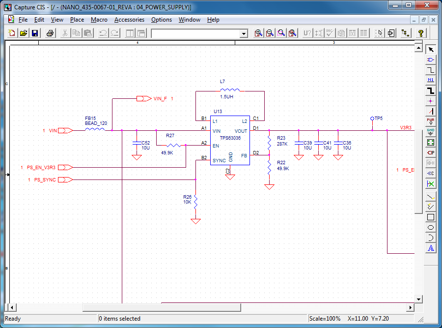
Schematic
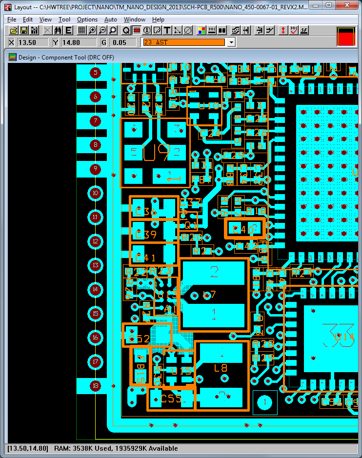
Layout: