This thread has been locked.

If you have a related question, please click the "Ask a related question" button in the top right corner. The newly created question will be automatically linked to this question.

Picking a fuel gauge adivce

Other Parts Discussed in Thread: TPA2013D1, BQ27542-G1, BQ27545-G1

Hello all,

I am building my own set of bluetooth headphones, and I am a little overwhelmed on what fuel gauge would be best for my application. Could someone offer some advice on what could be my best option?

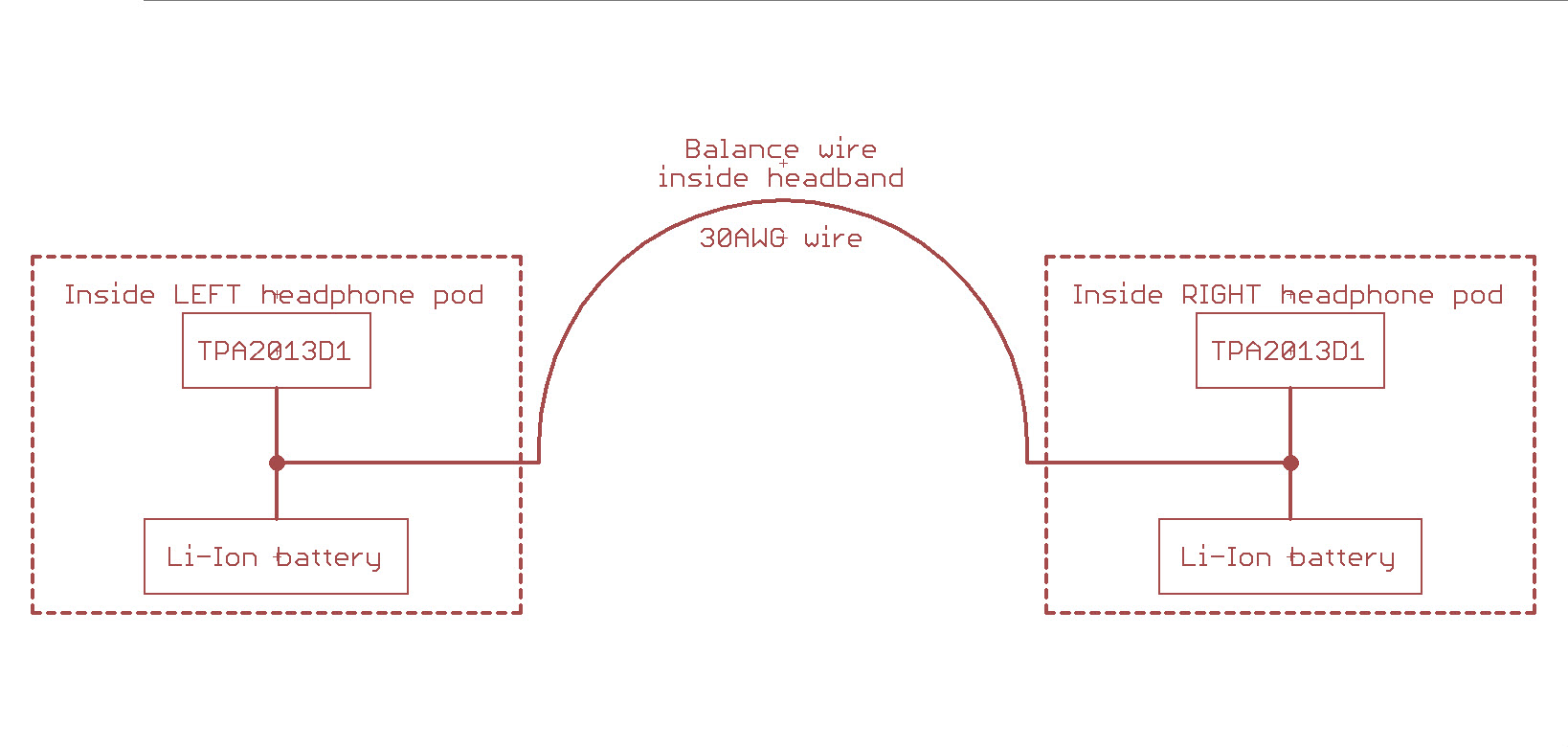
Inside each headphone pod(part that hold the speaker), there is going to be a TPA2013D1 amplifier with its own battery(300mA to 1000mA). Both the left and right side batteries would be hooked in parallel, with a pair of wires going from the left pod, across my head, to the right pod. That way both batteries would balance each other out, but most of the current draw would be done locally within the pod. I hope that makes sense.

For a starter, the batteries could be changed. I want to try different size batteries to find the best ballance between run time and weight. But after I find the batteries I want to use, they will not be removed until they go bad. 

I was thinking of putting 2 fuel gauges in the set. One in each pod, after the battery, and before the amplifier. The pair of wires i will be using to balance the batteries, would be after the fuel gauge. Then my micro would just take the information from each pod, and determine what the remaining capacity would be.

My thoughts for doing it that way, would allow me to know what the health of each battery is, and to allow me to know how each pod is performing. 

I am wondering if anyone would have an idea on what fuel gauge I should use? and/or a better idea. I'm open to any ideas I get. Only requirement I have is what packages I can use. One, I am pick & placing the parts by hand, and using a toaster oven to reflow the parts. Two, my board house has limits of 5mil/5mil trace and spacing, with 10mil holes. So most BGA packages will not work (0.5mm pitch)

Thanks for any, and all advice I get

Anthony

  • Hello Anthony,

    Sounds from your description that you will be using a 1s2p configuration, correct? With one cell per pod but connected in parallel via the wire that goes behind your head (I'm assuming). If that's the case, you would be looking at single-cell gauges, I recommend reviewing the Impedance Track gauges.

    We have two flavors for gauges: system side and pack side. System-side reside on the system board and allows the user to detach and replace packs. These system side gauges also include some additional host-interrupt functionality to allow the host to behave on interrupts and don't rely on polling the gauge for status. Pack-side gauges reside within the pack or are seen in embedded battery application where the pack will not be replaced.

    Since your end device will be using a fixed cell that won't be removed until it degrades, sounds like a pack-side would be a good option for you. You can review the bq27542-G1 as a pack side solution, it has a QFN package. I would imagine your PCB board size to be limited since the pods would be small. For a BGA solution, you might want to review the bq27545-G1 or bq27741.

    If you are using a 1s2p configuration, 1 gauge IC should suffice since it's considered a single cell configuration and the cells will balance themselves out since they are in parallel.

    Hope this helps.

  • Fernando,

    Thank you so much for the reply.

    Yes, that is correct, I am doing a 1s2p setup. Just the batteries are in different locations.

    I like the bq27542-G1. But the bq27545-G1 will not work because my board house can do trace size and spacing down to 5mil (0.005 in) 3.5mil would be needed for BGA packages.

    I have one question about using only one fuel gauge.... If I only have one set of wires tying both batteries together just to balance the batteries, Where do I put the sense resistor?

    Hopefully this will help understand what is going on.

    Left pod;
    ********************************
    *** Battery --------> amplifier ***
    ********************************
    |
    | Balance wire x2 (1 pos, 1 neg)
    |
    ********************************
    *** Battery --------> amplifier ***
    ********************************
    Right pod

    I will draw up a much better example shortly.

    Thanks
    Anthony
  • Fernando,

    Sorry for the delay, but here is a basic block diagram of the setup I currently have. This diagram only shows the power system, it doesn't show the DSP, microprocessor, or the bluetooth.  I hope this helps to better understand what I have.

    Thanks

    Anthony