This thread has been locked.

If you have a related question, please click the "Ask a related question" button in the top right corner. The newly created question will be automatically linked to this question.

BQ24610 charging profile incorrect, power switching not working.

Other Parts Discussed in Thread: BQ24610

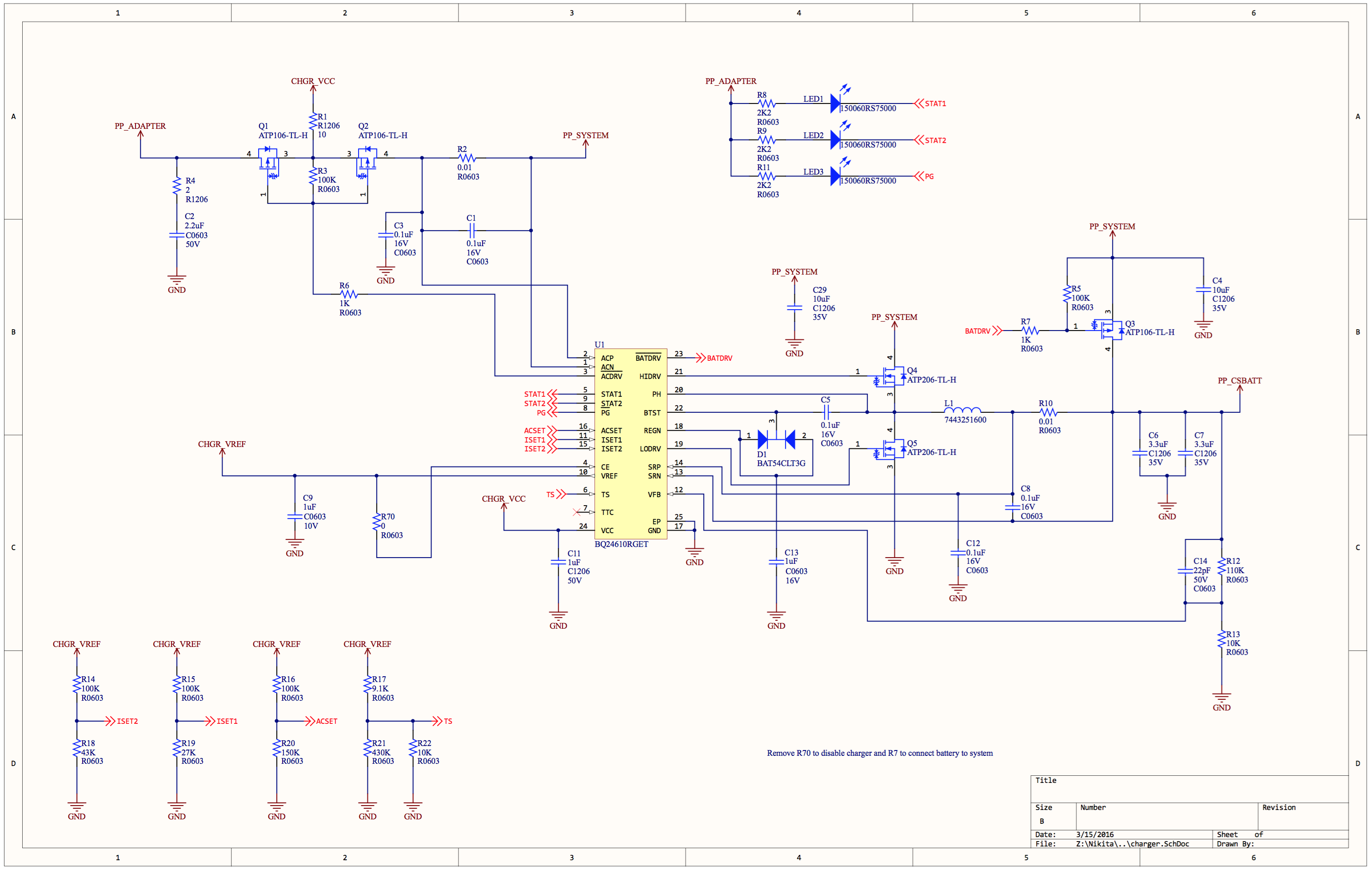
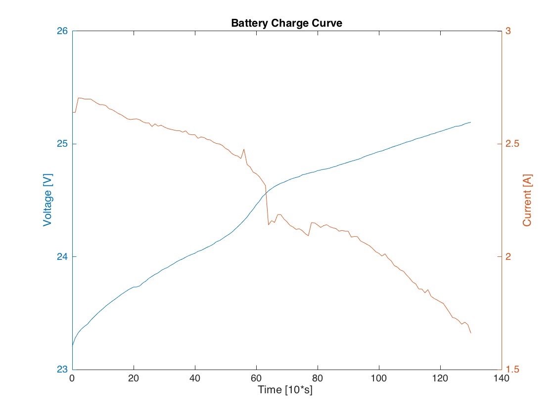
I am working on a charger for a 6S battery (25.2V fully charged) using the BQ24610. While testing the charger, I'm noticing that the current in constant current phase isn't constant, but steadily decreasing, and the voltage in constant voltage phase isn't constant, but steadily increasing past 25.2V. Once the current charge current is around 1.6A, an external battery meter triggers an overvoltage alarm, so I stop charging. When I reinsert the battery, it is detected as charged and STAT2 LED turns on. My charge current is set to 2.4A, however it starts charging around 2.8A and continuously drops. Below are my schematics and a charge profile that I measured up until the over-voltage alarm. 

Note: R19 has been changed to 15K on the actual board, TTC has been connected to VREF, and ISET1, ISET2 and ACSET have 1uF caps.

Also, I noticed that when I disconnect the battery from the system, the power to the system is momentarily lost. The other way (disconnecting AC adapter while battery is plugged in) works fine. What could cause this?

  • Hi Nikita,

    What is the input source rating (voltage, max current, max power)?

    What is the battery capacity and charge current rating?

    What is your system requirement (voltage range, max power, average power)?

    Some things to debug the problem:

    1. See if you can also graph input current as well. I'm thinking you are hitting input current limit and that is why your battery charge current is slowly going down. As battery voltage increases, you need more input power in order to maintain the same current output.

    2. Can I also see waveforms for PH node, BTST and REGN? There could be noise, making your charger system unstable.

    3. You may want to read the voltage measurement for ISET1, ISET2 and ACSET. Noise and resistor error may change your settings.

    4. VFB voltage may be noisy as well (2.1V at VFB is the regulation voltage for battery CV).

    On the schematic:

    1. C1, C3, C5, C8 and C12 need to be rated higher, probably 35V or 50V better.

    2. Recommended inductor is 6.8uH and output capacitors (C6, C7) should be 10uF 50V each.

    3. Do you have caps that are close to Q4 drain? At least have 2x 10uF 50V and a 1uF 50V.

    4. Add 0.1uF 50V caps in parallel to R3 and R5 to control FET turn on time.

    On the layout:

    1. Make sure you have the power loops close and small. Look at the following:

    As for your system power loss, is your input source dropping? It could mean that the system power requirement is making your system voltage drop, having to resort to using battery power through the Q3 body diode.

    Regards,

    Steven