Because of the Thanksgiving holiday in the U.S., TI E2E™ design support forum responses may be delayed from November 25 through December 2. Thank you for your patience.

This thread has been locked.

If you have a related question, please click the "Ask a related question" button in the top right corner. The newly created question will be automatically linked to this question.

LM5020 Duty factor variation

Other Parts Discussed in Thread: LM5020

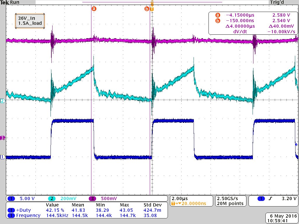
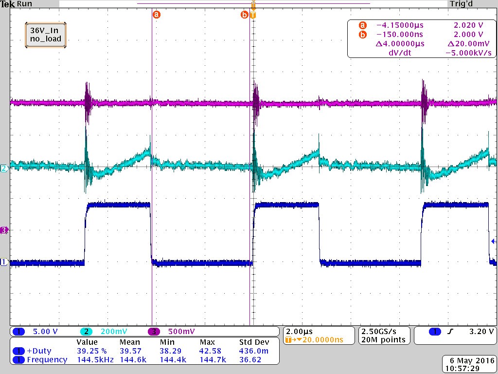
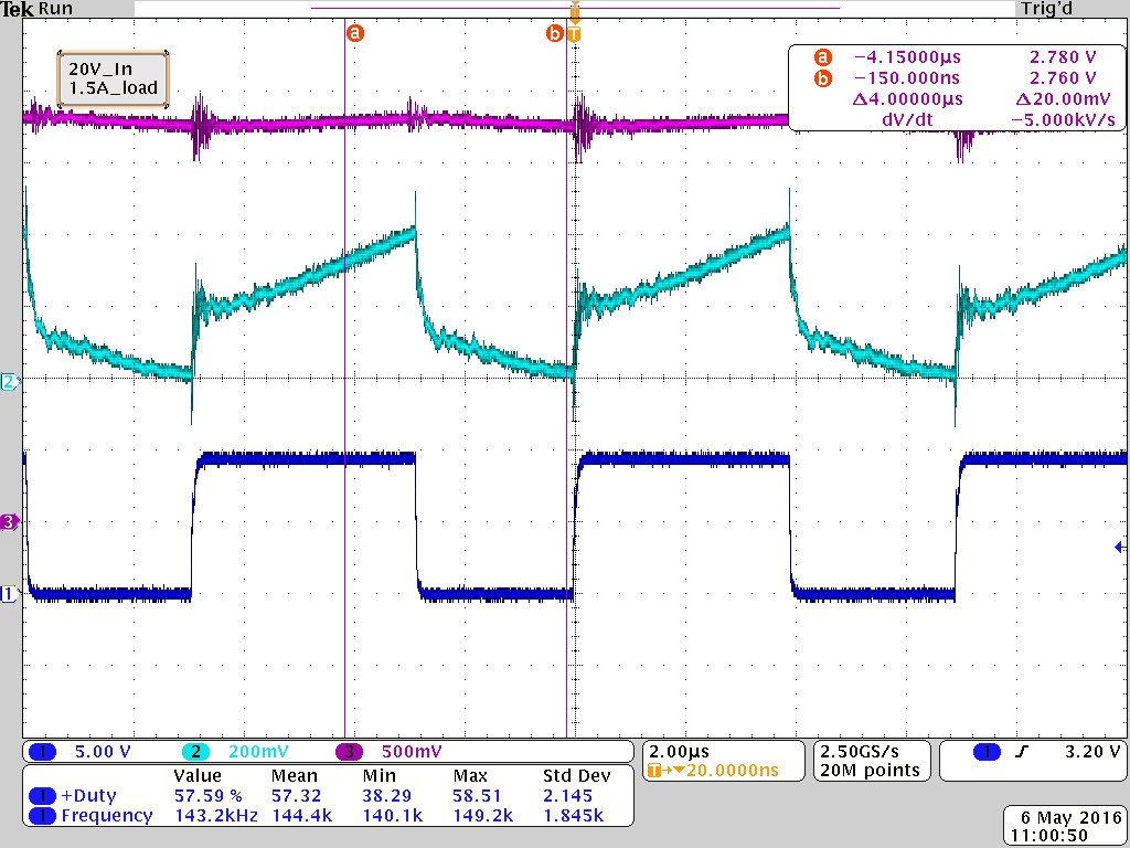
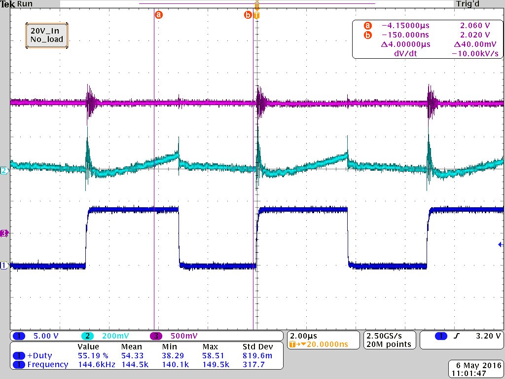
I am using the LM5020 in an isolated flyback configuration. The output voltage is well regulated over load, but I do not see any variation in duty factor at a given supply voltage. The COMP pin is driven by a MOCD207, and the FB pin is grounded. The scope plots below show trace 1-OUT waveform, 2-CS waveform, 3-COMP pin voltage. Is the duty factor only dependent on supply voltage? The COMP pin varies with no change in duty factor - is this correct operation?

Thank you

  • Hi Mark,

    I have asked one of the applications engineers to respond to your post.

    Regards

    Peter
  • The variation of duty cycle may well be slight with a variation in load.  it all depends on the amount the load is varying by and the impedance in the power path.  If the output is regulating, then it is likely the loop is doing what it is supposed to do.  If there is an issue in the loop, there would be a significant drop in output voltage 100mV's++ with a given load step.  The variation in duty cycle is greatest with a varying input supply voltage.  Can you perform a load step and measure the output voltage perturbation?  If you have concerns, you can post here so I can take a look?


    Thanks.