


Hello everyone, we are working with the LM5002 and we would like, if possible, to solve the following problem.
We are using the switching regulator to generate 24.5 V from Vin = 12 ~ 15V with Iout = 0,02mA, then passes through an LC filtering, a LDO that generates Vout=~ 23,5V and such voltage ends in two operational amplifiers. Below is an outline of the specified area: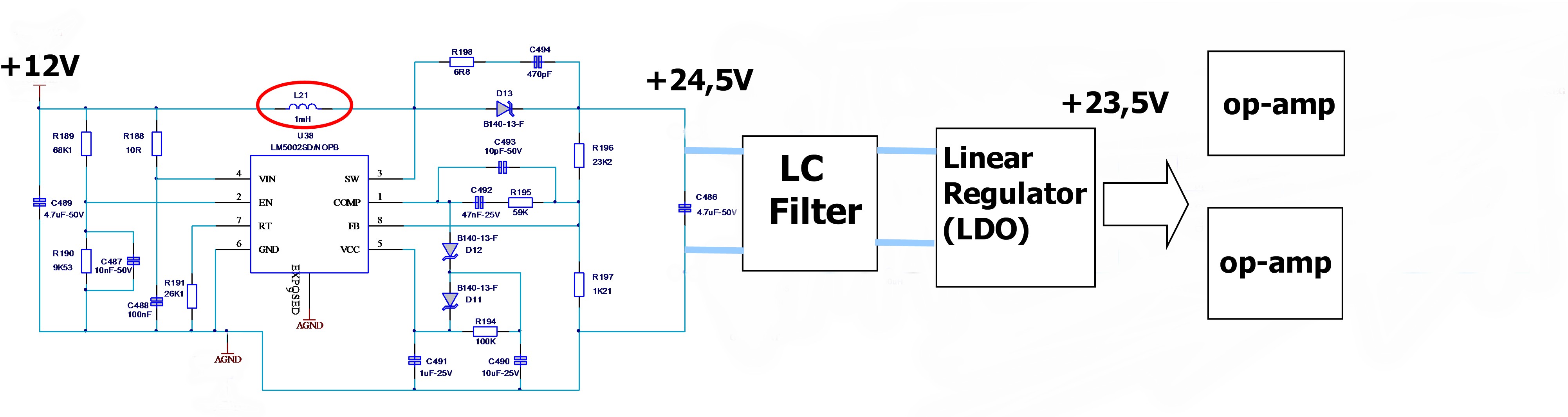
It's a prototype we have already mounted, tested on a pcb and it works very well, but sometimes, around 10% , the inductor (marked in red circle - part number LPS4018-105MRB) is usually burned and finally, giving a value of Vout=12,2 V approx.
We want to finish this design and we are afraid that this will happen again. We have used your WEBENCH® Designer tool, including the same components of the bill of materials and we have tried to follow the tips on the layout of PCB (we could provide the layout of regulador if necessary, because we know that the distribution of components is important).
Could someone please give suggestions on what could be happening?
- An overcurrent is quite rare, because the two op-amps consume 12mA, is quite low.
- The efficiency of regulator is around 65%. It is possible that for as little consumption, need other regulator / topology?
- It may be due to another component of schematic. ¿?
We are looking forward to your response.
Thanks and regards.