A related question is a question created from another question. When the related question is created, it will be automatically linked to the original question.
If you have a related question, please click the "Ask a related question" button in the top right corner. The newly created question will be automatically linked to this question.
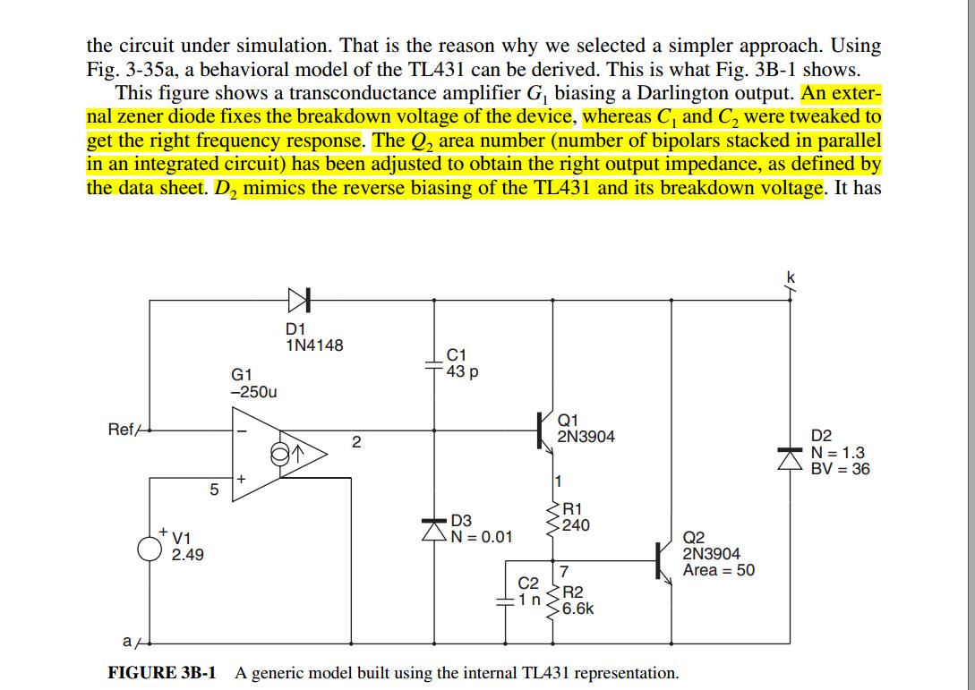
What's the function of the Diode D3 in the internal circuitry of TL431 ?
Jankel,
I've contacted the product group here. I believe the highlighted refers to D2. Are you asking about D2 or D3?
In general, you may also want to look into the much improved version of this device the ATL431.
Regards
John
oh, i'am sorry, the highlighted is only my note, it does nothing with this topic. Effective information for this topic is only the schematic in the picture. I guess that D3 plays a protective effect of proventing the 'BE' junction of Q1 from reversebreakdown,
Since this is a generic behavioral model that does not represent the actual TL431 internals, and D3 appears to be 'ideal' diode other than 'N=0.01' (Emission coefficient), I would guess that D3 is strictly to promote convergence by providing a current path to clamp G1 output at start-up when the Ref input is less than V1 (2.49V).
This question would probably be better directed to the author and/or publisher of figure 3B-1.