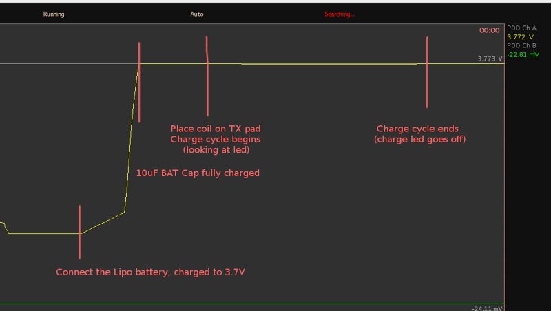
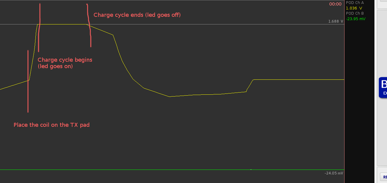
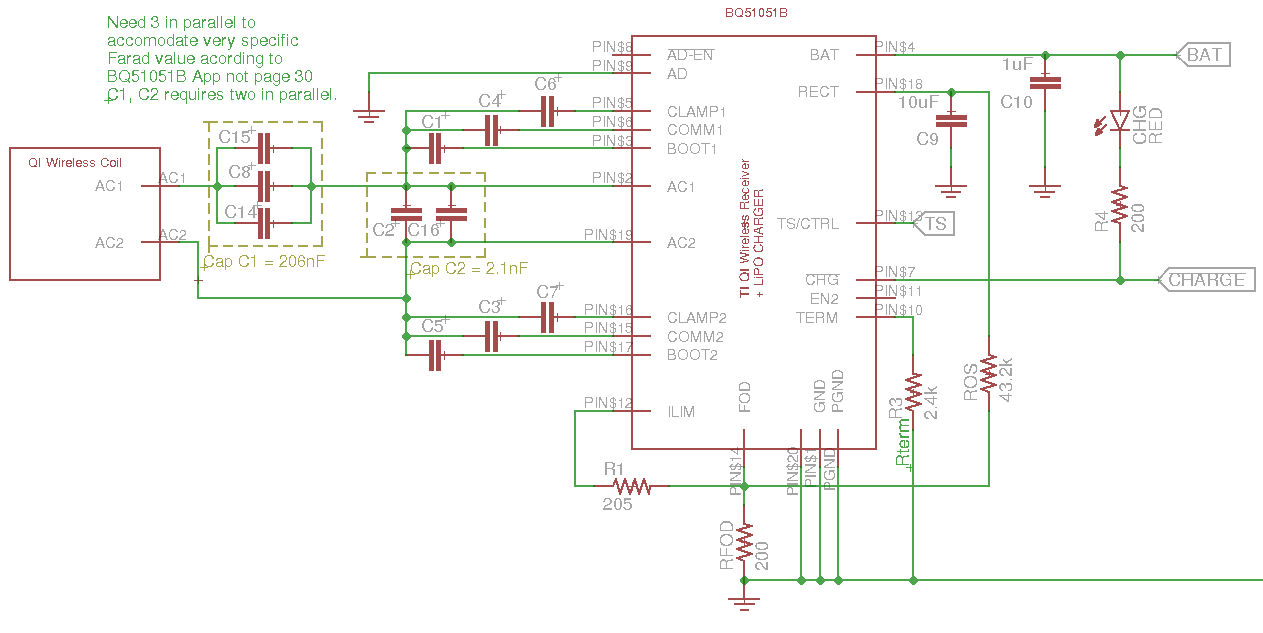
bq51051b stops charge cycle after about ~5sec. Schematic accordingly to appnote section 9.2.1 from www.ti.com/.../bq51051b.pdf
TS = 10k (no NTC function)
Coil might be a missmatch ? (http://www.digikey.com/product-detail/en/tdk-corporation/WR303050-15F5-G/445-16092-ND/4702658