This thread has been locked.

If you have a related question, please click the "Ask a related question" button in the top right corner. The newly created question will be automatically linked to this question.

RE: Driver for high frequency MOSFETS

Other Parts Discussed in Thread: LM5113

Dear Brett,

Unfortunately i'm coming back with another problem.

The LM5113 is generating the correct PWM waveforms and the mosfets work fine.

I'm using it in a synchronous buck topology. However, the gate driver somehow spikes above the threshold voltage of the mosfets at the falling edge, and the mosfets turn on again.

I tried testing only the gate circuit with an external low signal from the PWM controller and then apply externally a voltage at the mosfet gate, to see whether the LM5113 keeps the signal at the voltage level of the internal transistors, but this is not the case. The gate voltage spikes exactly at the external voltage, which means that the mosfet gate is open.

Shouldn't the LM5113 clamp the voltage at the internal transistor level, to prevent unwanted turn-on?

Originally i thought that it was a bad grounding problem, so i re-routed a new PCB with a very good ground connection, but still the problem remains.

What can be the cause of this, and is there a way to fix it?

P.S: i tried using an external clamp with diode and transistor, but still the same problem.

  • At this point, I really think this is more a question for the driver folks so I am going to move this thread over there.
  • Thanks, Brett.

    Hello Kolios,

    Could you please share the sch and PCB , as well as the tested waveforms? so that I could understand the case in a better way? Thanks a lot.

    Wei
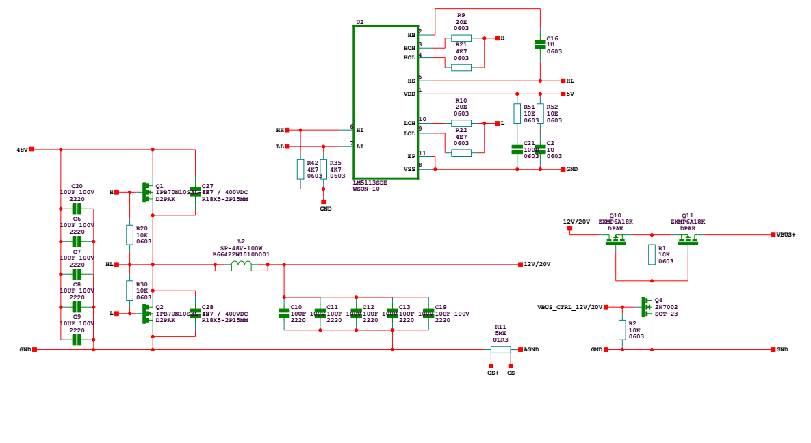
  • I attach my schematic and my PCB design.

    The low-side pull-don is wrong, but i have already fixed it in the PCB.

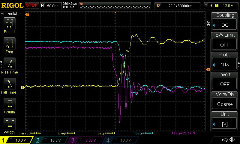
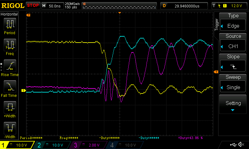
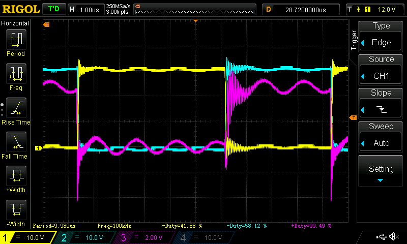
    The scope captures with the H-bridge operating are:

    (yellow: High side MOSFET voltage, blue: Low side MOSFET voltage, purple: High side MOSFET gate)

    I also tested only the gate without the inductor by applying a low signal from the microcontroller and a high voltage on the gate of the MOSFET, but its not pulling the gate signals low. Unfortunately I dont have the scope captures for that.

    Best regards,

    Panagiotis

  • Hi Panagiotis,
    Looking over the schematic and waveforms I would like to go over a few items.

    The waveforms look like they have a lot of ringing especially on the gate.

    First I want to ensure that those are real waveforms and have been captured using a ground spring on the probe to a ground in proximity of the gate instead of using a crocodile connection. That would help seeing what the real signal is.

    Now since the symptoms are present on the board, a few things that you would have to be aware of:

    1. The Qgd/Qgs (miller) ratio is important as high transient could force a voltage on the gate that might trigger it on. According to your schematic for the FETs you are using this is typical 11/16, which is normally fine, but the lower the ratio the better.

    2. You are using a 4.7ohm pull-down resistor, reducing the value of this should help maintaining the voltage on the gate closer to ground.

    3. The ringing on the gate waveform suggests that you have a lot of inductance on the gate current loop:
    a. Make sure you shorten that trace as much as possible and you allow the return current to be on the plane right underneath it. You could stitch ground return vias close to the start and finish points to help with that.
    b. Putting the resistors closer to the gate rather than the driver could help reducing the inductance on the second portion of the trace.
    c. Increase the trace width to reduce the inductance.

    4. I am not sure why you have 10ohm resistors in series with the decoupling capacitors for the LM5113, also the trace is long and thin and would and you are increasing the inductance for the driver loop.

    5. The LM5113 does not have the internal clamp (as you have pointed out) so when it is in an unpowered state there is nothing holding the node low. The best solution for this is to apply power to the LM5113 first; otherwise an external clamp is necessary.
    If the problem instead happens when the circuit is already running, then I suggest going over the points above.

    Best regards,
    Alberto
  • Alberto, Thanks very much for your kind help. Appreciate a lot.

    Panagiotis, let me know if you have further questions.

    Wei