This thread has been locked.

If you have a related question, please click the "Ask a related question" button in the top right corner. The newly created question will be automatically linked to this question.

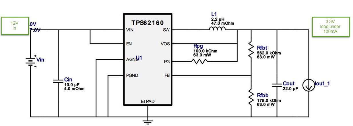
TPS62160 is unstable under the light load

Other Parts Discussed in Thread: TPS62160

I am trying to sue TPS62160 with 12V battery input and 3.3 V output with the load current under 100 mA - most of the time around 50 mA
When I look at the output without load its very stable but when connecting the load it starts moving dipping 200 - 300 mV from time to time with some repeated slow frequency  and i can see some small pulses somewhat repeated the input of the inductor?! The same works fine if input voltage is under 5 V
I've tried different value for the resistors as well ( 6.34 K / 2 K) and it seems slightly better but output still unstable!

When its without load I see short pulse with about 1Khz on the inductor input, and when load is connected the pulses goes with much higher frequency 100Khz +  so seems the regualtor is workign but does not hold the voltage
Any idea what is happening and what can be done to make it stable and hold the voltage under the load!?

Thanks,
Eugene

  • Can you post waveforms of Vin, Vout, SW, and inductor current that show what you describe? Can you post your PCB layout?
  • Hi Chris,
    Thank you for answering. yes I can provide some addtional information but I though you can let me know if there significant difference in the operations when it powered from 5 - 7 V and 12 V?!
    Basically the exact same circuit works fine when its powered from 4V battery and up to 6 - 7 V, but when its powered from 3 x batteries ( about 12V ) its not stable and dropping voltage about 200 - 300 mV...
    I've tried three devices and al lbehave the same way, when I low the input voltage is stable and holds 3.3 V as well as with the load disabled. I've tried when Enable is connected to the input voltage or controlled with the logic level - same.
    So any idea why it is behaving differently even though it claims to work 3 - 17 V? Any specific limitation? It seems that its entering power saving mode from time to time - the load current in the range of 50 - 60 mA

    Thanks,
    Eugene
  • No, there is no difference in operation as Vin is varied. This is why I need to see waveforms and your layout to see what is happening.
  • OK, I will try to collect the info and publish - do you need both when its powered from 4 V and from 12V or only from 12V?

    Again if there is no specific need to be addressed for the 12V input why its working for 4V and does nto work for 12 V?

    Does increase in inductor value ( using 3.3 or 4.7 instead if 2.2uH) or output cap can help?

    Thanks,
    Eugene

  • Yes, you can post waveforms for both Vin conditions.

    A picture is worth a thousand words. Showing me what your circuit is doing is much better than using words to explain it.
  • Hi Chris,

    Sorry for the delay - will post shortly.

    I have another question - I am using this regulator to power up WiFi module and I am planning to be able power down the module to save the power.

    As I understand it can be done using Enable pin or disabling the coming power through the MOSFET.( disconnecting the GND for example )

    What kind of voltage level has to be maintained on the Enable input  pin in order to completely shut down the regulator - is it has to be the same as input voltage or I can use just logic 3V or so for it?

    On all the reference schematics Enable is connected to the Input voltage so want to conform if logic level will work with the inout voltage of 12V and  the output is 3.3V
    Thanks,
    Eugene

  • The logic levels required for the EN pin should always be shown in the device D/S. For this IC, you can find them on page 5.