This thread has been locked.

If you have a related question, please click the "Ask a related question" button in the top right corner. The newly created question will be automatically linked to this question.

UCD9090 GPIO based Enable configuration

Other Parts Discussed in Thread: UCD9090

Please find below some of our queries related with UCD9090 Device programming

 1. Is the VMON11 dedicated only for temperature measurement? By anyway can we configure this pin for voltage monitoring?

Kindly refer the below tables with MON pin connections for voltage monitoring in the UCD9090 Device.

Pin Name

Pin#

Monitoring Voltage

MON1

1

+5v

MON2

2

+1.8v

MON3

38

+3.3V

MON4

39

+2.5V

MON5

40

+1.8VD

MON6

41

+1.0V

MON7

42

+1.35V

MON8

45

VTT

MON9

46

S1VDD

MON10

48

+1.5V

MON11

37

+3.3VD

Answer for Question#1 will decide whether our connection of +3.3VD with MON11 is valid or not.  

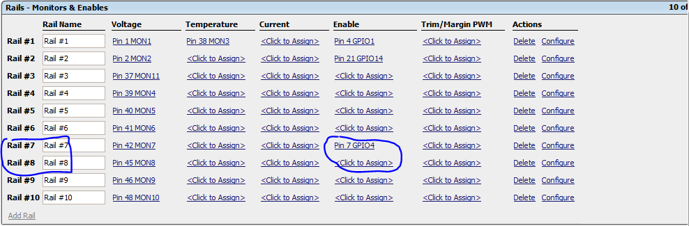
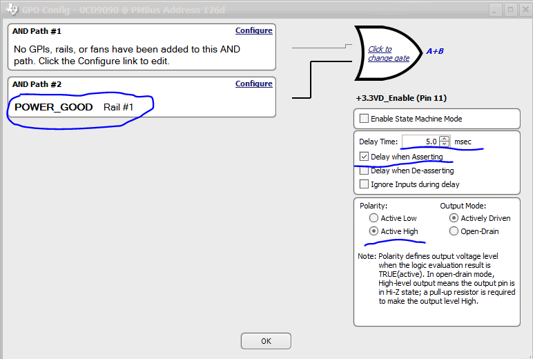
Below table talks about which GPIO used as enable signals, that enables one or more regulators.


Pin Name

Pin#

Net Name

Enabling Voltage Rails

GPIO1

4

P_ENABLE1

+1.8v

+2.5V

+3.3V

GPIO2

5

P_ENABLE2

+1.0V


GPIO3

6

P_ENABLE3

+1.5V

S1VDD


GPIO4

7

P_ENABLE4

VTT

+1.35V


GPIO5

10

P_ENABLE5

+1.8VD

+2.5VD


GPIO6

11

P_ENABLE6

+3.3VD


 Now our challenge is, in the tool we were not able to assign same pin (GPIO) for multiple rails. For eg. As per our above representation, we should have Pin4 GPIO1 for all there rails #2, #3,#4. But when trying to do so, once the PIN4 GPIO1 is assigned for one rail, for other rails that pin is not available to assign. Kindly refer the snap shot


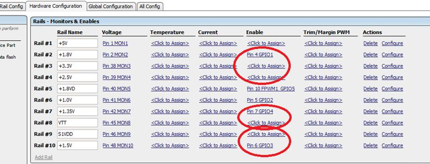
Help us to resolve this assignment issue.

  • Hi,

    [1]  For the MON11 pin,  when the input signal of ADC is below 0.2V, the conversion results may be inaccurate. So as long as this inaccuracy will not affect your application, you can use MON11 for voltage monitoring.

    [2] For the enable assignment, we cannot assign the same GPIO to several  power rails by GUI. But you can have this connection on your PCB board. If so, Please pay attention to your configuration.

    For example, if we want Rail #7 and Rail #8 to share the same GPIO, as below:

    firstly, configure Rail#7 and Rail#8 to be fault shut down slave of each other, as below:

    then, go to Fault response window of both Rail#7 and Rail#8, configure the fault response as "Shut down immediately". 

    thanks,

    Luke

  • Hi Luke,
    Thanks for your immediate reply.
    On#2, yes we have taken care of assigning same GPIO Enable to multiple voltage regulator enable pins as per the power sequencing requirement in the schematic and layout. I will do the settings that you recommended
    On#1, we have connected +3.3VD rail with the MON11 Pin(potentially divided to have 2.5V at pin) for monitoring and we have taken out the corresponding Enable signal from GPIO6 and connected with the +3.3VD Load Switch (actually a load switch which delays the +3.3V for specific ms and gives out +3.3VD). But if MON11 pins good to go with voltage monitoring, how can i now drive the enable signal through GPIO6, since this setting wont be coming into the "rails-monitor&enable" window.

    I have done the configuration and uploaded the project file into the UCD9090 device and powered up the board, all enable signals are giving out proper voltage levels and enables the respective regulator. Except the +3.3VD enable GPIO. It shows low.

    Related with this, will it be possible to initiate the Enable/Disable signal through GPIO straight a way without including the monitoring conditions.

    Kindly give some insight on this.

    Regards,
    Felix.
  • Hi Felix,

    You can assign GPIO6 as the Enable signal of rail #11, as your description, the +3.3VD rail will follow +3.3V rail after a specific delay. So you can go to the Logic controlled GPO window to configure it, shown as below:

    The GPIO6 pin will follow PGOOD signal of +3.3V rail after a specific delay.

    For the MON11 pin. I think it won't work if you straightly use it to monitor +3.3VD (the 11th rail), cause UCD9090 can only monitor 10 rails. My suggestion is :

    [1] No need to change the layout, keep the connection between MON11 and +3.3VD , but assign the MON11 pin as current monitor for rail +3.3V on GUI. Only in this way, MON11 will be actived. And you need to have your own coefficient between the current(on GUI) and voltage(real +3.3VD rail).

    [2] since you have already monitored +3.3V rail, I think there is no need to monitor the +3.3VD rail.

    Best

    Luke