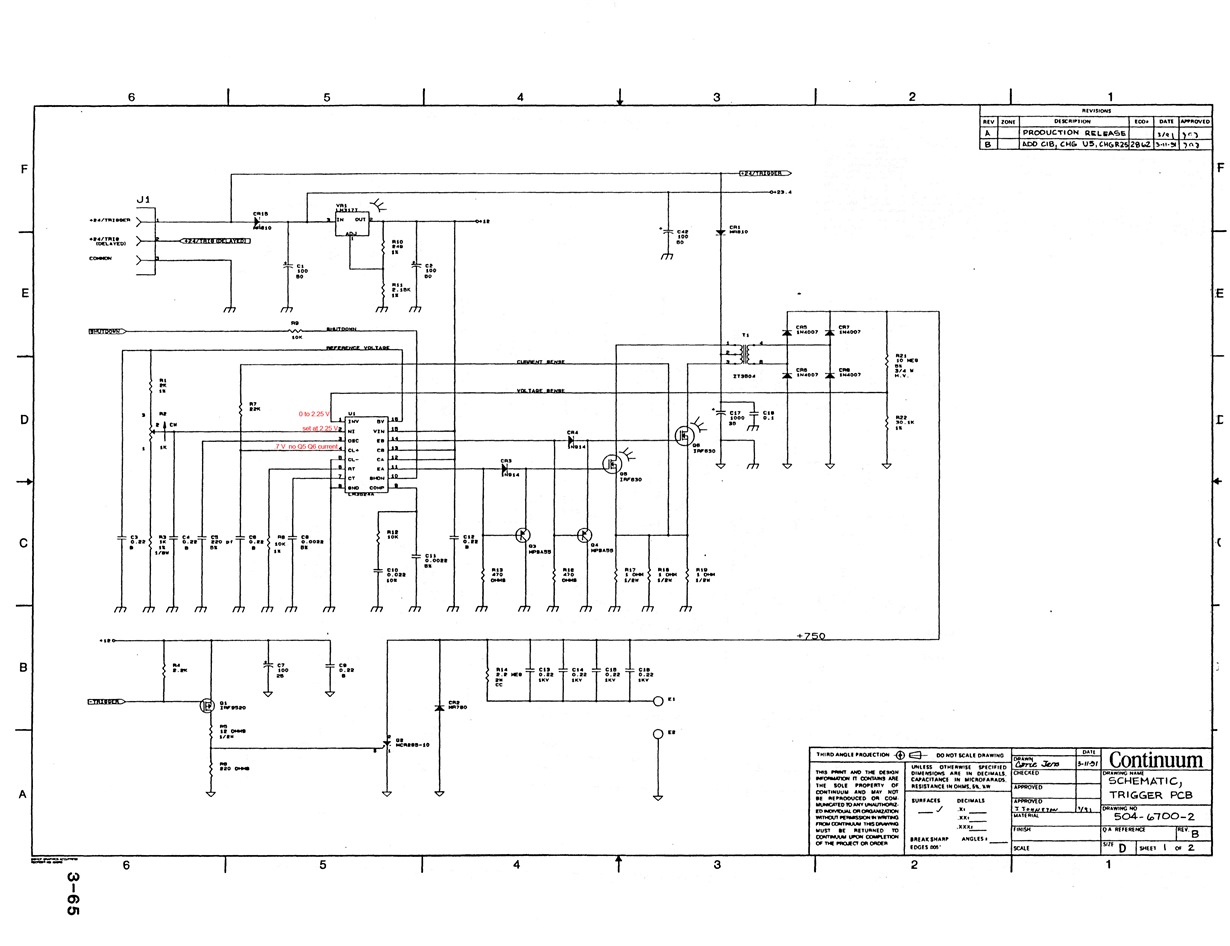
Problem with a circuit board from a commercial laser (circa 1988) employing an LM3524 whose emitter output pulses drive several MOSFETs. Ultimately, 24 VDC pulses are stepped up through a transformer and rectified; the LM3524 maintains a stable level at around 750 V. Here's where I encounter difficulties: To limit maximum current, the output current of the MOSFETs is monitored through a 22k resistor going to +CLSENSE (pin 4); -CLSENSE (pin 5) is grounded. The problem is that even with zero MOSFET current Pin 4 is ALWAYS above the ~0.2 V shutoff threshold for pin 4 (Pin 4 around 0.7 V with zero current fed back); thus the LM3524 emitter outputs are always shut off--circuit doesn't work: no ~750 VDC produced. The same observations of shutoff at Pin 4 are made with a similarly wired LM3524 on a prototype board. The circuit board in question definitely worked at an earlier time. I don't understand how it could have worked, except if I surmise that it formerly worked because a circa 1988 LM3524 had different specs on the CLSENSE inputs, such that there was no shutdown with zero MOSFET current using the present feedback arrangement to Pin 4. First, please comment on whether this is the case. (If not, what could possibly be the problem?) If this surmise seems correct, then with a present day LM3524 how should the circuit be modified? The modified circuit should cause LM3524 shutoff at what was intended to be the I(max) shutoff threshold in the original circuit.
-
Ask a related question
What is a related question?A related question is a question created from another question. When the related question is created, it will be automatically linked to the original question.


