A related question is a question created from another question. When the related question is created, it will be automatically linked to the original question.
If you have a related question, please click the "Ask a related question" button in the top right corner. The newly created question will be automatically linked to this question.
Please also describe the circuit environment. Is there a lot of RF noise nearby? Is there a lot of ripple on the input?
Unfortunately, when this happens to me it usually means that the pass-fet is destroyed or shorted. But I assume that you would never accidently connect anything incorrectly in the lab (as I often do), and so, I would be happy to review your schematic and or continue this discussion till the problem is uncovered.
Assuming that everything in your design is correct, then this problem that you describe should not happen.
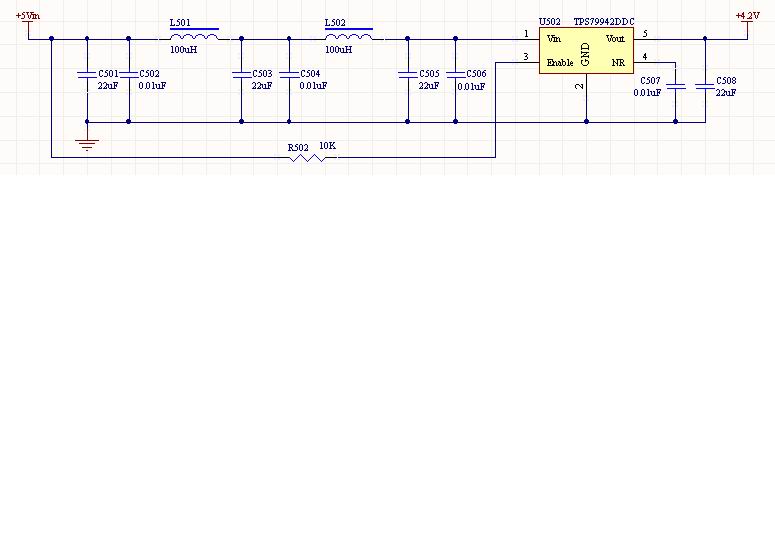
The first thing to check is that the TPS79942 is grounded. Use an Ohm meter to make sure the ground pin of the TPS79942 is physically connected to the ground of the board. If it is then you have probably damaged the pass transistor as Bill mentioned. The pass transistor can be damaged by applying reverse input voltage. The pass transistor can also be damaged by overvoltage on the input. Check VIN during power up to make sure there is no overshoot that will apply too much voltage to the TPS79942.
Your schematic looks fine. I see that you are taking many precautions against startup transients and overshoot. Have you found the problem yet?
Have you tried powering-up the circuit from a 5V lab supply (instead of the ac-dc of the ac-dc adaptor)?
Our first concern is that the ac-dc adaptor output overshoots above 7V absolute maximum rating on the Vin pin. And our second concern is that the combination of inductors and ceramic capacitors on the input is forming a Hi-Q resonance that causes an overshoot on startup that destroys the part.
I have no speculation as to why the Cnr capacitor would cause the output to change. Apparently the circuit is not very happy.
Does the part immediately go to 5.192V output on startup? What happens when you disconnect the load? Normally when we see a sinusoidal output we suspect that the circuit is unstable. Is the oscillation present immediately at startup? When you try turning on the circuit with the lab supply perhaps you can try bypassing the input filter to see the effect.
As an added precaution, perhaps new sample parts should be ordered for the case that your present parts have been damaged in some way.
Thank you very much for your particular analysis.Just mow,I tested my ac-dc adaptor ,the output overshoot is about 6.5V,dosen't above 7V.As your advise,I'll try more scheme,such as use a 5V lab supply or bypassing the input filter or oedered some new sample parts.I'll try my best to solve the problem.If there is any progress,I'll post it here to share and discuss.
Thank you again!Best wishes!You are really very kind!
Thank you!My problem has been solved.The problem lies on the ac-dc adaptor.The output of my AC-DC adaptor may rush up to 6.5V when starting,so that my TPS79942 was damaged.I changed a lab power supply and a new TPS79942 chip,then the problem was solved.
My suggestion is: the power supply(that can damage the COMS gate) as well as the Cout(that can make the output instable) is important for the Linear Regulators.


