This thread has been locked.

If you have a related question, please click the "Ask a related question" button in the top right corner. The newly created question will be automatically linked to this question.

UCC28950 uneven pulse width between OutC and OutD during start up.

Other Parts Discussed in Thread: UCC28950

I am working on a 400VDC PFC input, ZVS PS FB power supply with 3.6KW output at 24V/150A.

Transformer is running at 85kHz, with turn ratio at 12:1 and Bmax at 0.22T at steady state.

A cracking noise is heard during the unit power up. Transformer saturation is observed due to magnetic flux walk away. The unit survives as CS pin comes to action.

Marking on the chip is

UCC28950

16TG4

AH6S

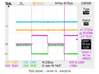
I checked the circuit at 57Vdc input voltage with synchronous rectifier disabled  and output current was set at 15A. Waveforms were captured below. Figure 1 and Figure 2 shows the difference in the pulse width of OutC and OutD from UCC28950. OutC and OutD pulse will matches with each other in pulse width after start up.

How can we get rid of the uneven pulse during power up?

=================

Input Vdc 57V; Output at steady state 2.75V/15A

C1: Center tap of pwr traffo, 2nd side; C2: OutB PWM IC; C3: OutC PWM IC; C4: OutD PWM IC;


Figure 1                                           Figure 2

 ===========================================================================

C1: Center tap of pwr traffo, 2nd side; C2: CS PWM IC; C3: OutC PWM IC; C4: OutD PWM IC;


Figure 3

====================

 C1: Center tap of pwr traffo, 2nd side; C2: Vo Output; C3: OutC PWM IC; C4: OutD PWM IC;

Figure 4

============

  • Hello Chung
    I think that the uneven OUTC and OUTD pulses you are seeing are due to the controller changing the duty cycle on the transformer. You can see that the current pulse in Fig 3 changes width as the PWM comparator terminates the switching cycle – this will show up as a change in the OUTD OUTC pulse length. Of course in normal, steady state operation OUTC and OUTD don’t change.

    Can you check the soft start function during converter startup. It should be at 0V and then ramp to 3.6V at which time it would rise rapidly to about 4.6V. At the same time, please observe Vout - this is to make sure that the soft start ramp is long enough to allow the output voltage to reach its setpoint.

    Are you running the system in Voltage or Current mode control?

    Have you checked that the amount of slope compensation you are using is correct – don’t forget that slope compensation is needed in Voltage mode control too, not for ‘normal’ running but it is needed for stable operation in current limit.

    The current sense signal looks to be very heavily filtered – this will cause problems in Current mode control and also in Current limit in both Current mode control and Voltage mode control.

    Regards
    Colin
  • Hello Colin,

    Thanks for your reply.

    To my understanding the UCC28950 is running as a phase shift full bridge controller IC. It means the driving pulse width is changed by varying the phase between the output pair outA, outD and OutB, OutC, not by varying the pulse width between OutC and OutD - unless the pulse is terminated by the CS.

     I did check the SS pin. Please find the figure 5 and figure 6 below. The uneven pulse occurs when SS is around 0.68V.

    ==========

    Figure 5

    =============

    Figure 6.

    The unit is running at current mode control with 68kR as Rsum, tied to return. It provides slope compensation around 0.08V/uS. In figure 3, the peak voltage of CS is around 1.2V that should leave a wide margin to the CS triggering point.

    Furthermore, if CS did cut in, the output voltage should be capped or run into hiccup mode. However, in figure 4, the output voltage keeps on rising as the triggering settings of figure 1, 2, 3 and 4 are the same.

    As recommended in the design note, the current sense filter is 1KR + 330pF. The waveform is similar to the waveform illustrated in the application note.

    Your comment please.

    Regards,

    ISO Chung

    =====================

    Interesting finding on  6th June 2016

    Found difference in switching frequency: during start up at 78.74kHz (figure 8) and steady state at 85.47kHz ( figure 9).


    DC operation; Power on housekeeping circuitry only

    SS shorten to around 2ms.

    C1: EA+ PWM IC; C2: SS PWM IC; C3: OutC PWM IC; C4: OutD PWM IC;


    Figure 7

    ===========

    Figure 8

     =======================


    Figure 9

    =============