I am investigating the efficiency of the driver LM3406HV. I am working with a demo board (http://www.ti.com/lit/ug/snva407b/snva407b.pdf). I am feeding 4 red LED with 0.356 A DC and 25 V. Each LED exhibits 2V voltage drop. I calculated the driver efficiency dividing the overall LEDs strip voltage drop multiplied by the driver output current by the power supply voltage multiplied by the overall current that it supplies to the circuit, i.e. I divided the electrical power fed by the driver to the LEDs by the total electrical power supplied to the circuit. By doing so I get a power efficiency equal to 40%. It does not seem to agree nor with what is declaired in the datashet neither with the result of the simulation (http://webench.ti.com/appinfo/webench/scripts/SDP.cgi?ID=44C17AF323A05425). Since I can not get rid of this, I would like to ask you a couple of questions: 1) Is the mentioned efficiency really a power efficinecy? 2) Am I doing something conceptually wrong, like comparing something different from what is compared in the datasheet? 3) Is it possible that the evaluation board so strongly affects the efficiency measurement? Just to resume: - DRIVER: LM3406HV - LEDs N.: 4 - LED COLOR: RED - LED VOLTAGE DROP: 2 V - LED RESISTANCE: 5.5 Ohm - CURRENT: 0.356 A - DUTY CYCLE: 100% (DC) - SUPPLIED VOLTAGE: 25 V Experimental result: - P_OUT/P_IN = (V_OUT*I_OUT)/(V_IN*I_IN) = 0.4 Simulation result (http://webench.ti.com/appinfo/webench/scripts/SDP.cgi?ID=44C17AF323A05425): - Efficiency = 0.8 PWM and output voltage
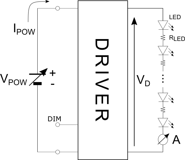
This is, instead, the setup used