This thread has been locked.

If you have a related question, please click the "Ask a related question" button in the top right corner. The newly created question will be automatically linked to this question.

Regulator layout for TPS84410

Hello,

I am getting an occasional drop out on my regulator. I believe that part of the issue is I am getting noise coupled into the feedback path (which is located on the bottom layer of my design). I was able to minimize this by adding a faraday shield on top of the feedback path and this helped quiet my supplies. I am however still seeing the occasional dropout and I wanted to know if I could have someone in your group take a quick look at my PCB layout.

Regards,

Guy

  • Additional information

    Vin = 3.3V

    Vout1= 1.0V

    Vout2 = 1.8V

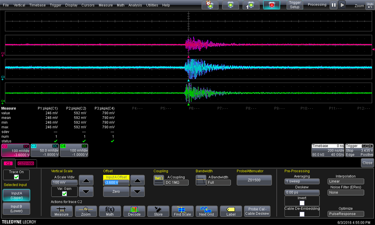
    I captured an event.

    the red trace is my input

    blue trace is my 1.8V output

    green trace is my 1.0V output.

    I can think of two things that might cause this ringing

    1) not enough input cap

    2)layout issue -  possible coupling into my sense feedback line

    Have you seen this type of signature before? any suggestions. This hit might occur once or twice an hour when I am running stress tests on my PCB.

  • I received your email offline. I will request schematic and layout files to help understand what might be causing this noise.