This thread has been locked.

If you have a related question, please click the "Ask a related question" button in the top right corner. The newly created question will be automatically linked to this question.

LM5175 designed for 12v giving 3.8v output

Other Parts Discussed in Thread: LM5175EVM, LM5175, LM5175RHFEVM-HD

Hi All

I have built a power supply using LM5175 using the reference schematic of LM5175EVM.The required output voltage is 12v at 5A. The schematic is attached below. All the components used are same as the one given in BOM.

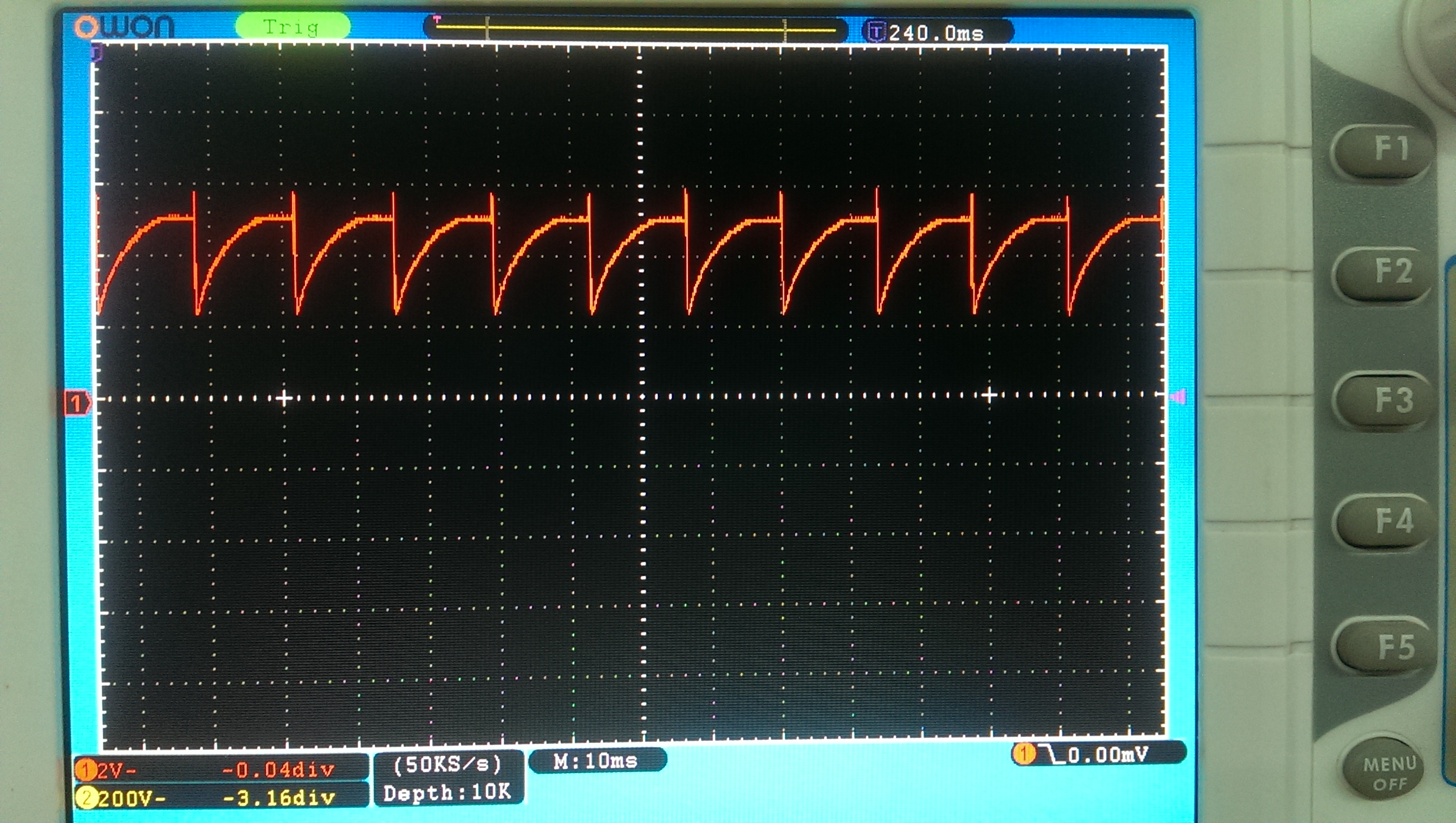
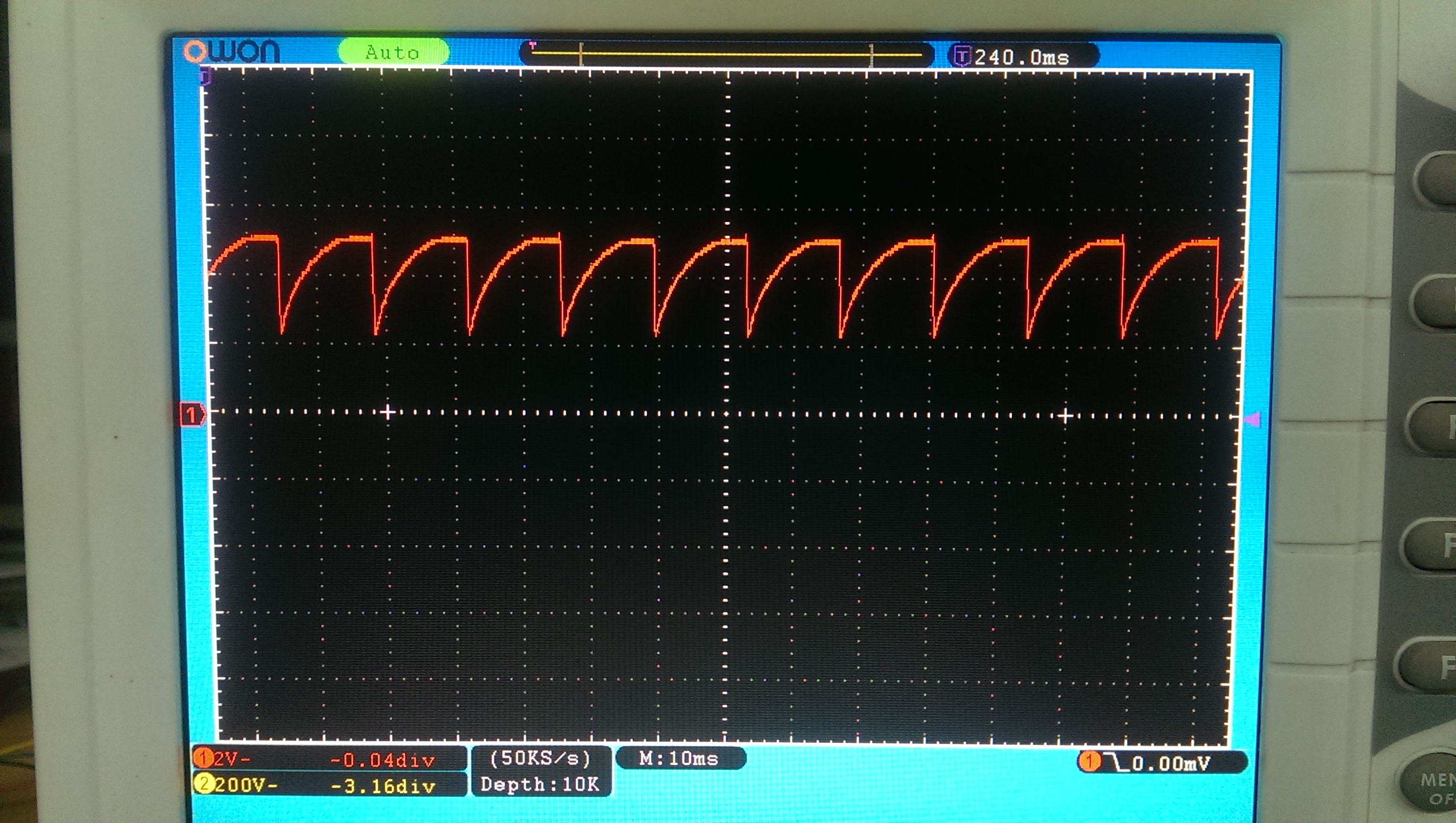
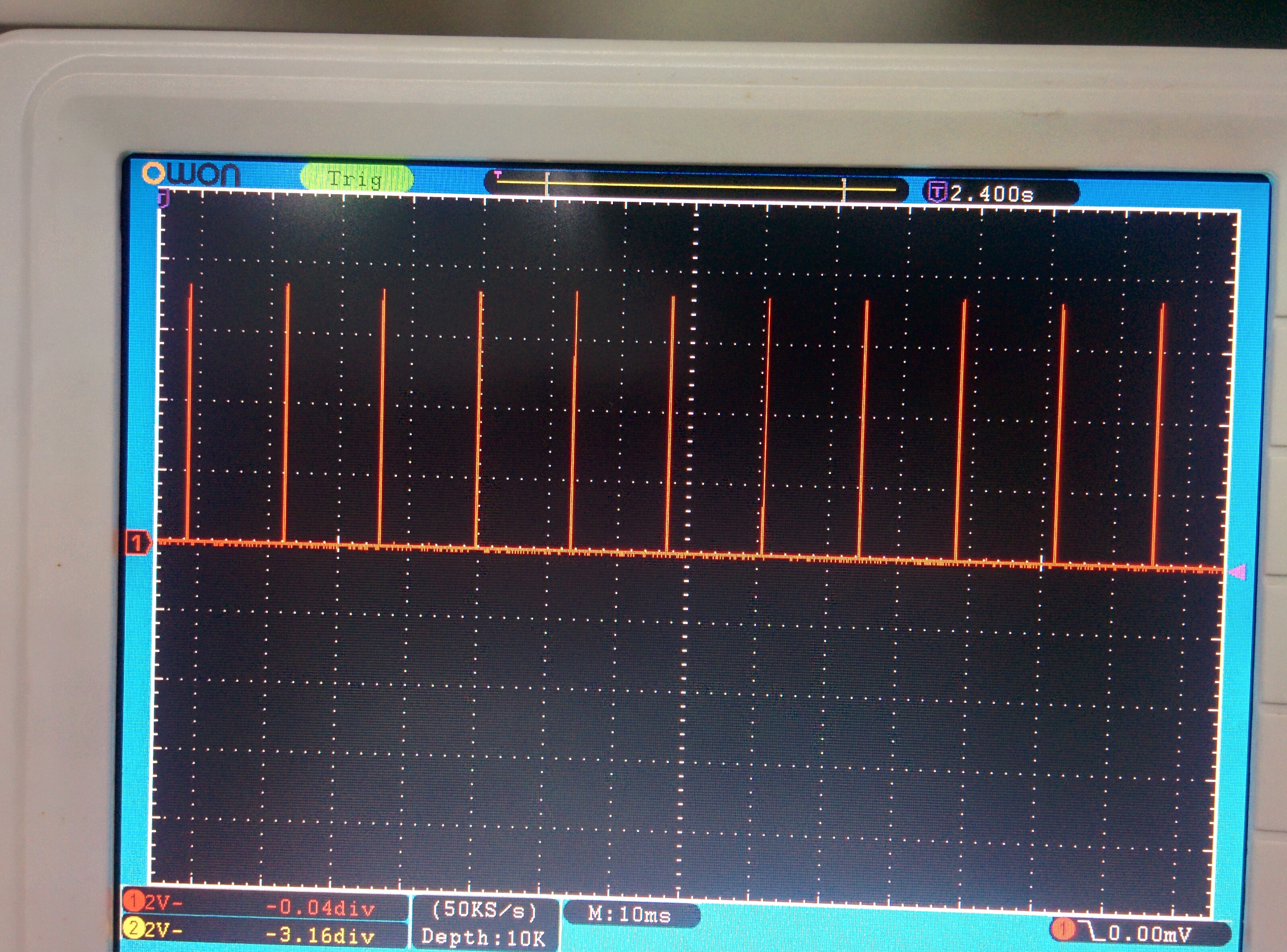
The output voltage I am getting is -1.5V.

When i change the mode to CCM by changing R11 to 93.1K and removing R7, the output voltage is 3.8V.  Kindly suggest any corrections to be done.

tidrha1.pdf

  • Hi Hemaditya,

    I think we need more information. A good approach is to make sure all the connections are good and components are soldered properly.
    I would start with
    VIN
    EN
    VCC pins.

    If these are ok, then please look at the switch nodes (SW1/2) to see if they are switching.
    If they are, we need to look at the waveforms to try to figure out what is going on.

    Thanks and regards,
    Vijay
  • Hi vijay

    sorry for the delay, I have checked all connections. They are good and components are soldered properly

    The voltages at

    EN is 1.96V

    VIN is 11.85V

    VCC is 7.41V

    These are the waveforms at sw1 and sw2

  • This does look strange. The next logical step is to check the following nodes:

    SS: Is it ~1.26V or stuck at some lower value.

    LDRV1 and 2: Is there any gate driver output?

    Since the switch nodes are not reaching ground during switching I suspect that the low side FETs are not turning on.

  • Yes the ss pin is at 0V.

    There is no gate drive signal at LDRV2

    and the signal at LDRV1 is like this

  • Hi,

    Something is obviously broken. SS should start ramping up when EN is > UVLO threshold. If all teh connections are ok, I suggest replacing the LM5175 and see if the part was accidently damanged.

    It may also be a good idea to use LM5175RHFEVM-HD or one of the other EVMs from LM5175 webpage and modify the circuit to what you want. This eliminates any unknowns with the board/assembly.

    Regards,
  • Hi vijay

    I have actually tried with 3 ic's with different values of components. one circuit with values given in application schematic in datasheet of lm5175. the other with one of the EVM schematic. All have given same kind of outputs. Anyways I shall assemble another board with LM5175RHFEVM-HD schematic.

    I have few queries

    1,Which are the most important pins which govern the output voltage?

    2.There are 2 mosfets  BSZ0902NS in LM5175RHFEVM-HD. Can i use BSZ042N06NS instead of that because I only have them.

    3.The inductor, I only have 4.7uH.Is that ok.

    4.Is there a way to test if LM5175 is in good condition.

    Thanks & Regards

    Aditya

  • Hi Aditya,

    I suggest you contact your local sales agent to order an LM5175 evaluation module (or you can order on the web). It will be much easier than building your own to get started.

    Other comments:

    4.7uH is ok.

    It is ok to use the same mosfets for all 4.

    I am still trying to figure out why SS is 0V. The problem might not be in the schematic.

    It would be good to get rid of all connections to the basic buck-boost circuit that is non-essential.

    A few things that come to mind are: any connections to FB node (other than FB resistor divider).

    I will also short the ISNS+/- pins (use C18 pad).

    R7-> open

    R8-> use 100k

    SS must ramp up for teh converter to start.

    Regards,