A related question is a question created from another question. When the related question is created, it will be automatically linked to the original question.
If you have a related question, please click the "Ask a related question" button in the top right corner. The newly created question will be automatically linked to this question.
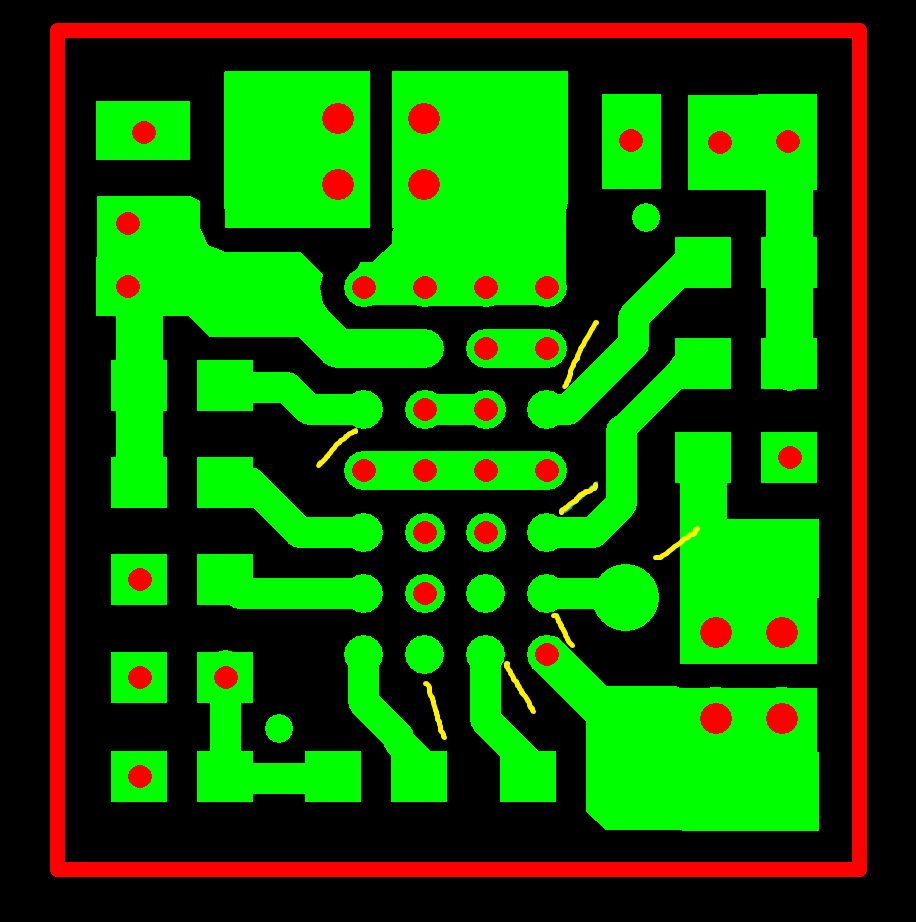
I do not believe there are any missing drill holes. I'll cover the nodes you have marked based on the IC pin number. The layout shown has A1 in the top left. The whole top row is PGND.
C1 and C4 are Boot 2 and Boot 1 respectively. They are tied to capacitors on the top level.
E4 is COMM1 and is tied to a a capacitor on the top level.
F4 is CHG# and is not used and therefore is left floating. The pad attached to F4 is only a test point for debug purposes.
G2 is EN2 and is left floating (internally pulled low).
E3 is TERM for the bq51050B and is tied to a resistor on the top level (or EN for the bq51003 and left floating - internally pulled low).