This thread has been locked.

If you have a related question, please click the "Ask a related question" button in the top right corner. The newly created question will be automatically linked to this question.

LM5035C / Latched Overload Protection

Guru 29720 points
Other Parts Discussed in Thread: LM5035C

Hi Team,

The figure 26 of datasheet shows "Latched Load Over-Voltage Protection" feature.
In this time, my customer considers to "Latched Overload Protection" feature, so I would like to ask two questions.

1)
My customer considers the following schematic to achieve "Latched Overload Protection".
If a current limit is detected, a few uA of 22μA current source flow into 1MΩ resistor from RES pin and LM5035C enters standby mode, disabling the drivers and enabling 23uA current source on the OVP pin, then OVP voltage will remain more than 1.25V.

Is it reasonable schematic for "Latched Overload Protection" feature?
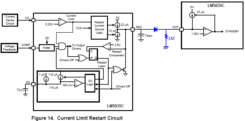


2)
If the solution of 1) isn't possible, is there any solution for achieving "Latched OCP feature"?

Your support would be appreciated.

Best Regards,
Yaita / Japan disty

  • Yaita,

    I think it would work if the following concerns are addressed,

    1. 1M resistor for latching operation is too large, 1M*23uA=23V which is greater than the max rating of OVP pin, i.e., 7V. The latch resistor value should be selected such that the OVP pin voltage is lower than the max rating in latch mode, such as 150k.

    2. The voltage drop of the added diode can't be too large, otherwise the OVP pin voltage may not get higher than 1.25V (threshold for triggering latch operation) when RES pin voltage reaches the peak value of 2.5V.

    3. Since the OVP pin normally is tied to the input via resistors to achieve OVP, you will need to adjust the original calculation after adding the diode and latch resistor.

    Regards,
    Wangxin
  • Hi Wangxin-san,

    I appreciate for your support.
    I would like to confirm the following.

    Regarding question 1, I believe OVP pin doesn't increase more than 5V even if 1M resisor is used because internal 23uA current source is from 5V reference.
    Is my understanding correct?

    Best Regards,
    Yaita

  • Yaita,

    Although it appears in the block diagram that OVP pin voltage would be clamped to 5V REF, but in reality, the OVP pin voltage can't be too large in order to ensure normal operation of the current source.

    Regards,

    Wangxin