This thread has been locked.

If you have a related question, please click the "Ask a related question" button in the top right corner. The newly created question will be automatically linked to this question.

UCC28710 No Output

Other Parts Discussed in Thread: UCC28710

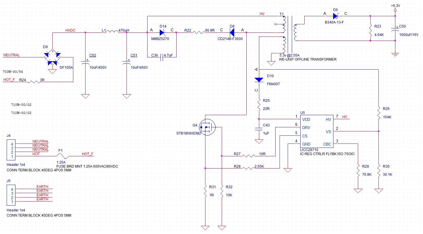
Hey everyone, I would appreciate any input on my AC/DC PSU problem. I have done the design using UCC28710 and followed the suggested circuit from WEBENCH. However I do not get any output from my circuit and I cannot figure out why or where to start my debugging. Here are some details about the design.

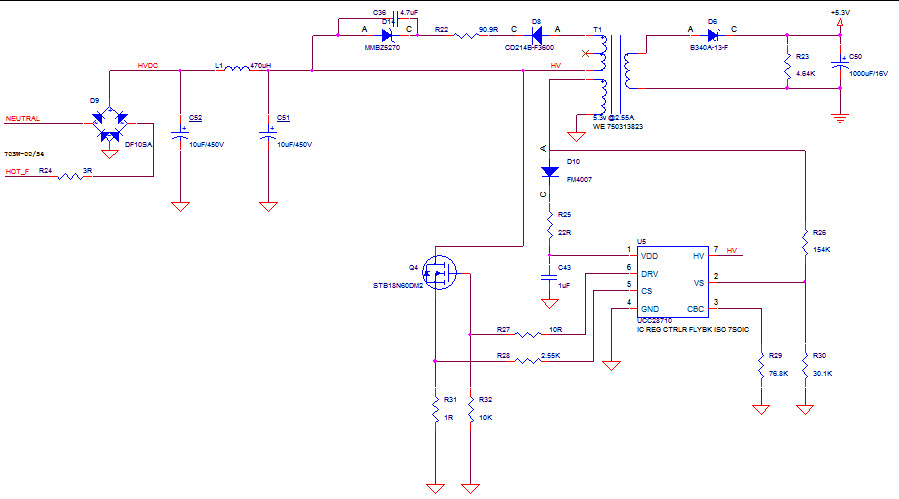
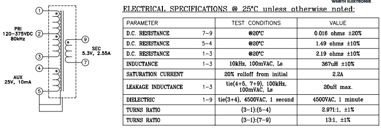
The transformer used is from Wurth PN: 750313823


The mosfet is from ST PN: STB18N60DM2

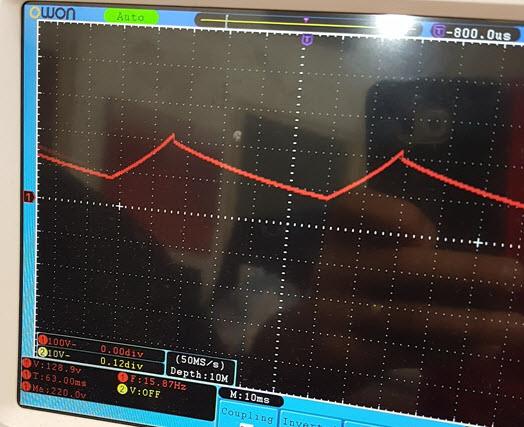
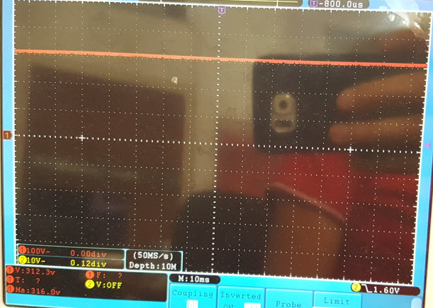
With the above circuit I get 0V on C50 and around 7V on VDD, I am not sure what is causing this. So any help is appreciated.

Thanks again

  • The turn on UVLO of UCC28710 is 21V so it is behaving properly by not switching.  What is the input voltage you are attempting to turn on at?

    It appears that the primary windings of the transformer is incorrectly connected since they are shorted out.  The windings need to be connected in series between HV and the source of the FET, and the clamp needs to be connected in parallel across the output.  Below is how it should be configured.  Also if you did not explicitly design the snubber I recommend reading this app note http://www.ti.com/lit/an/snva744/snva744.pdf 

  • Hey Eric, first thank you for the reply.

    Second yes you are correct the circuit in the photo is wrong, but the circuit on the board is the one you showed not the one i posted. I was trying to make some tweaking on the schematic to figure out the problem and ended up posting the wrong photo, sorry for that. The correct one is below. 

    I didn't explicitly design the snubber, I copied the one from WEBENCH. I will check the app note and get it fixed. But I wouldn't think the snubber will make it shutdown completely, would it ?!

    I supplied the circuit directly from the mains, 220VAC.

  • I missed another problem, the dot polarity on the transformer is incorrect. For flyback converters the dot from the input and output need to be on opposite sides since it's actually a coupled inductor. You can do this by swapping pins 4 /5 and 9/7, or just pins 1/3.
  • yes I noticed this, that is why i was trying to switch the circuit. I tried switching the polarity (1-3) without any luck, but I will give it another try on a fresh PCB and let you know. thanks again.
  • When you run the next tests can you please share waveforms that show HV, VDD, DRV and the output of the bias winding if there is still an issue?
  • I switched the primary winding (1-3) and gave it a run, still no luck. I will get the oscilloscope and send some shots of the signals you requested.
    At the meantime using the voltmeter I made some measurements that didn't make sense to me.
    Voltage from Pin1 to Pin4 of UCC28710 (VDD): 14.55V but the voltage on D10-Anode to Pin4 (Aux voltage) is 0V.
    Anw I will get a better look with the scope and post back here.

    Also I tried changing the load resistor (R23) value, removed D8, removed Rcbc.
  • Unless  Vdd ever exceeds 21V those measurements make sense.  With the UVLO threshold at 21V the FET will not turn on at that point, so no voltage will be generated on the bias windings .  Currently Vdd is being generated from the HV startup pin, which looks to be properly connected to the HV bus.

    Double check to make sure nothing is loading the Vdd pin and holding the voltage low, and that HV is at the voltage you expect.

    For reference PMP9202 a TI Design that has similar operating parameters, so you can compare your design to it to see if there are any variations that may be causing problems.  It looks like there is a startup issue, so I'd focus around HV and Vdd to make sure they are doing what you expect.

  • I went back to the datasheet and I agree with your analysis, now it makes more sense to me. Still not sure why VDD is not reaching the corresponding level though. HV is at 300VDC which is what I expect. I tried to put a bigger cap but still no luck making it start.

    But now at least I know where the problem is, and I will try to isolate VDD to see what happens. Thanks again.
  • Here are the scope shots. HV looks good but VDD is not. Drive is flat 0.

    I tried changing the capacitor value on VDD but still it didn't work.

    VDD is 12.89V not 128.9V as written in the photo below.

    HV is 312.3V stable

  • What is the volts/div for the Vdd waveform? Is it charging up to 21V, then dropping to about 8V? If so this shows that the UCC28710 is starting in a fault condition, so it's preventing the converter from operating. Section "8.3.2 Fault Protection" on page 12 in the datasheet goes into more information about what can cause faults. I recommend checking the signals that are going into the UCC28710 during startup to make sure none are causing faults.
  • Also what load condition are you starting in? Can it start in a light or no load?
  • I just want to say I finally made it work, thank you for your help and for pointing me in the right direction. 

    1- Transformer pins 1-3 are swapped
    2- Assembly problem with the pull-down resistor on the MOSFET gate.
    3- After I fixed those two, I got a flickering output. I recalculated RLC(R28) based on the formula in the datasheet. I changed the value from 2.55K to 1K.

    It seems that the output is steady now, I will make more testing to see how it goes.

    Thanks again