This thread has been locked.

If you have a related question, please click the "Ask a related question" button in the top right corner. The newly created question will be automatically linked to this question.

LM5116 - Discontinuous mode

Other Parts Discussed in Thread: LM5116

Hi everyone,

I designed the schematic of a switcher with following characteristics:

Input voltage: 40-84V

Output voltage: 24V

Output current: 0-4A*

It goes from 100mA to 4A continuously and that's what bothers me!!

Please find my schematic below.

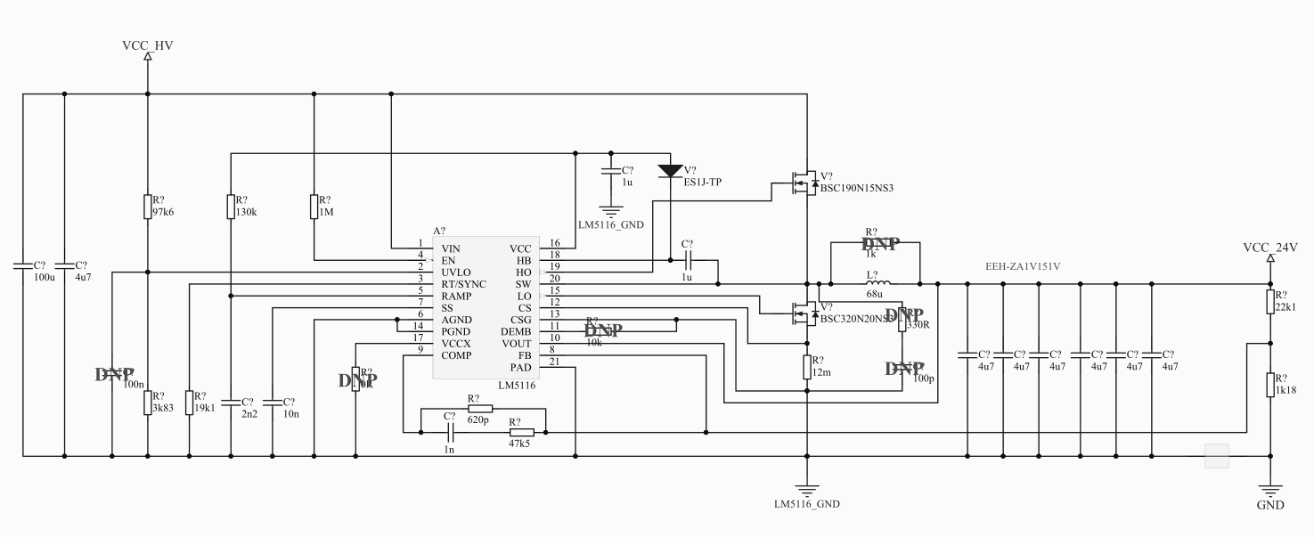
I've designed the circuit using Webench and datasheet example and I am concerned about discontinuous current mode and efficiency at light load(~100mA). I know that at this power stage switcher is only as good as it's layout, but unfortunately I don't have the layout yet. What could go wrong at light load and how to prevent that?

  • One question more regarding the input capacitors, Webench could not suggest me any useful input capacitor so I've decided to use 47uF Organic Aluminum Capacitor(lower ESR than usual Aluminum Electrolytic) in parallel with 100nF and 1uF(not shown on schematic). Would that be enough?
  • Let me see if I can get someone to help you.

  • tuvOk,

    What efficiency are you seeing and at what loading condition? At light load the gate drivers and core losses of the inductor dissipate the most power. Gate driver losses can me minimized by selecting a MOSFET with low total gate charge. Inductor core losses can be minimized by making sure that the inductor is selected correctly for the load range.

    Input capacitors are usually selected based on the amount of acceptable input ripple voltage, and is recommend to be no greater than 5%. Ceramic capacitors are usually selected as they have low ESR and can handle large ripple currents. 47uF seems a like a reasonable value.

    Thanks,

    Garrett
  • Hi Garrett,

    Thank you for your reply. Operating values are given by webench, and at light load(~50mA-100mA) overall efficiency is 40-50%, and LM5116 junction temperature is at 90°C. MOSFET's are cold though, nearly as ambient temperature. But we can assume that switcher will work at 200mA(74.56% efficiency) most of the time with still extremely hot IC(90°C). 

    Regarding the input capacitors, which capacitors to use when ceramics are not suitable enough due to high input voltage? For example, 5% of the worst case scenario is 40V*5%= 2V. If my input ripple current is approximately Iout/2 then that's 2Amps. Required iinput capacitance for that situation using the datasheet formula is Cin=Iout/(4*fsw*Vripple) = 3uF. My first thought was to use 10-15uF ceramics to compensate tolerance /DC-derating and some small 1000pf in parallel. I assume current RMS rating is not crucial  comparing with al. elco.

  • tuv0k,

    There are ceramic capacitors rated to 100V that would fit your design parameters. Aluminum electrolytic will work also but as you mentioned you will need to make sure that the ripple current rating is not violated.

    -Garrett