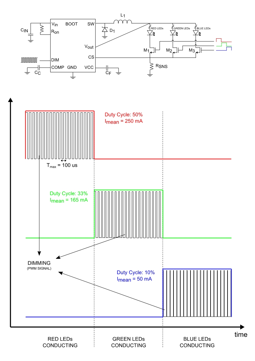
My purpose is to drive three different string of RGB LEDs with the same chip, in order to select different colors, which can vary in time.
Since the LEDs are very sensitive to thermal stress and in order not to damage them, I would like to drive the LEDs strings with a current dimmed at high frequency (>= 10 kHz). On the other hand, since I do not want to have strings of LEDs of different colors in parallel (because of their different bias voltage), the dimmed current must flow into each string at a time for one third of the period.
The basic configuration is shown in the attached figure, where the LM3406HV chip is shown together with red, green and blue LEDs strings. Each string is in series with a FET, whose gate is driven by a logic signal with a frequency of 100 Hz and a duty cycle of 33.3%. If the three logic signal are kept in phase, the current flows into each string separately for one third of the time.
Meanwhile, the dimming pin of the chip is fed with a PWM signal whose frequency is around 10 kHz and whose duty cycle can vary accordingly to the active LEDs string. In fact, in order to select the correct colour intensity, the duty cycle of the dimming signal must be able to vary in phase with the transition of the logic signal which drives the switches, as shown in the logic signal diagram of the attached figure. The maximum possible duty cycle of the dimming signal is 50%.
By now, I have individuated the driver LM3406HV, which allows a peak current of 1.5 A and has a dimming pin.
I wonder if the proposed configuration anyway affects the proper working condition of the LM3406HV chip, with particular attention to the required inductor L1. I resume the working conditions:
- PEAK CURRENT: 1.5 A
- DIMMING FREQUENCY: 10 kHz (or higher)
- DIMMING DUTY CYCLE: <= 50% and varies in phase with gates transitions
- LOGIC FREQUENCY: 100 Hz
- LOGIC DUTY CYCLE: 33.3%
I take the opportunity to ask if a LED driver exists, which is able to draw 1.5 A of peak current, which can be dimmed at least at 10 kHz and which possibly does not require neither an inductor nor an AC/DC converter.
A final question: I already individuated a solution to implement the switches, but I am looking for suggestion on this point as well. In particular, the gates must be able to draw a peak current of 1.5 A and must have a rise and fall time equal or less than 1 ms, in order to be driven with a logic signal at 100 Hz.
Thanks in advance for the helpful answer,
Best regards,
Marcello Simonetta
-
Ask a related question
What is a related question?A related question is a question created from another question. When the related question is created, it will be automatically linked to the original question.


