Hi,
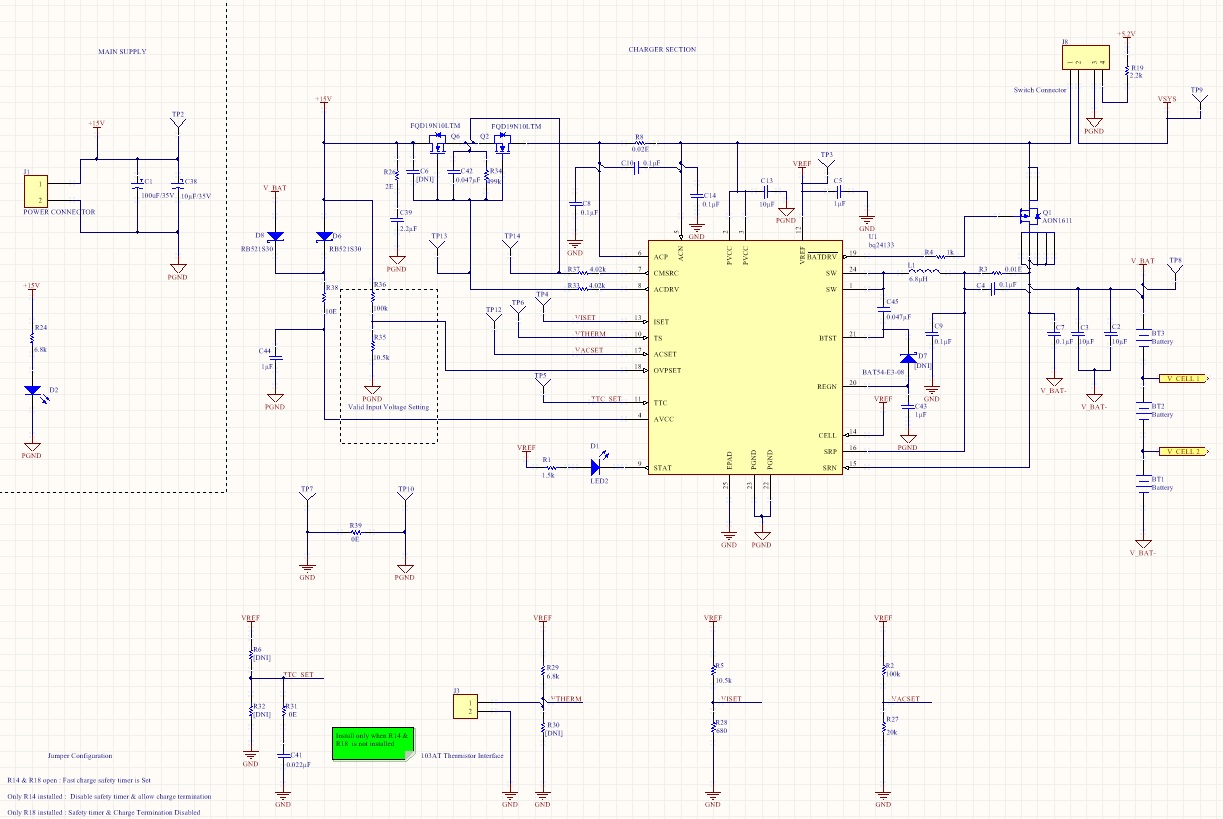
We have designed a battery charging circuit based on BQ24133 Charger IC in the initial version board works well and it has few layout mistakes i corrected and done second revision board, but the second revision board the moment i turn on the charger the fault status LED starts blinking, can any one help me to fix this.
Here is my Input and other conditions
Charge Input Voltage: 15V @1.5A
Charger current (Iset) : 1A
ACSet: 1.4A
TTC Set: Pulled low
Thermistor: 103AT
Number of Cells: 3 (each 4.2V @2500mAh
Voltage measured when fault LED blinking
VBAT: 10.26V
SRN: 10.26V
SRP: 10.26V
VISET: 0.2V
VTherm: 2.09V
VACSET: 0.54
TTC: 0V
Vref: 3.3V
Vregn: 5.95V
VACP & VAC: 15.09V
VACDRV: 20V
VCMSRC: 14.7V
voltage between BTST to SW pin am getting only 300mV but as per the datasheet it should be min 4V to charge i haven't got any reason why it is in 300mV and SW pin is in DC level there is no switching happening, and at this condition it takes only 6mA current from my charge input,
i have attached my schematic here, battery ground and charger IC ground are connected through 10m ohms sense resistor to monitor battery charger which is connected in BQ3055 battery gauge