A related question is a question created from another question. When the related question is created, it will be automatically linked to the original question.
If you have a related question, please click the "Ask a related question" button in the top right corner. The newly created question will be automatically linked to this question.
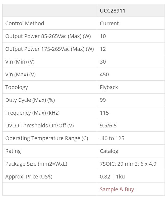
For low input voltage 60-90 V, the UCC28910/1 would not be suitable - they are not guaranteed to start below 100 V, and the internal FET Rdson would be too high - they are intended for offline AC-DC applications.
However, you could consider the UCC28704 device and use it with an external FET. This device is intended for CV/CC operation. However, since it is PSR (primary-side regulation), it does not use opto feedback, and instead uses the aux bias winding for feedback. As a result, the CV and CC accuracy for output voltage and current regulation may not be good enough for your application - to be conservative, the CV/CC regulation accuracy could be up to +/-5%.
You could also consider the UCC28740. This is a similar device, but it allows opto feeback to be used to get better CV regulation accuracy. This device also supports CC mode output current limiting, with the same +/-5% accuracy.
The UCC28740 includes a HV startup pin, which is again intended for >100 V applications. In your case, you could leave the HV pin open, and instead use a startup resistor from the DC input voltage rail to the VDD pin.
TI also offers a large selection of battery management IC's, which could be deployed on the isolated secondary side to manage the battery charging. The main power supply could then just be a generic Flyback to generate an isolated 5-V rail to feed the battery charger IC.