This thread has been locked.

If you have a related question, please click the "Ask a related question" button in the top right corner. The newly created question will be automatically linked to this question.

Analogue Fan control using TPS61085

Other Parts Discussed in Thread: TPS61085, PMP9774

I'm using the TPS61085 to convert 5V to 12V to run some 3-pin fans. I'm controlling fan speed using PWM and N-mosfet. However this messes up the tacho signal, so I'm thinking of using a variable voltage supply to the fan to control its speed.

Can I use a digital potentiometer on the feedback resistors to vary output voltage between 6V to 12V? Will this have any effect on the compensation network?

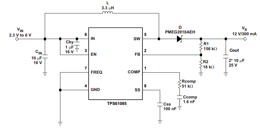
I've used the reference schematic from the TPS61085 datasheet. I have used the following values in compensation network

Rcomp = 59k

Ccomp = 1nF

L= 4.7uH

I was thinking of replacing R2 with a digital potentiometer to obtain output voltages between 6 and 12V. How easy is this to achieve and are there any other issues that might crop up?

Thanks

  • Dear Sir,

    Yes, you can use a digital potentiometer to realize the function. If you want to let :Rcomp = 59k Ccomp = 1nF L= 4.7uH, please make sure the "effective" ourput capacitance is higher than 10uF (so at least use 2*10uF considering the DC bias), higher output capacitance helps on the stability.


    If you can , you can also realize this function by amplifiers, you can check the PMP9774 for the detailed information. But this document use another IC, so you  just check the implementation idea.

  • Hi Helen

    Thank you very much for your answer. I am already using 4x10uF+1x4u7 capacitors on output side.

    Can I change the resistance while the switching is taking place, so that the output voltage changes while TPS61085 is running? Or do I have to disable converter first, then change potentiometer resistance value, then re-enable converter again?

    Thanks
  • Hi Helen

    For this application, I am thinking of using TPL0401A-10DCKR.

    I am keeping R1 at a constant 66.5k

    For R2 - I have split that into two parts. One part = constant resistor, 7.5k. Second part = variable resistor, between 0ohm and 10kohm.

    When I change the value of the second part of R2, I can vary output voltage between 12.2V (at 0ohm) to 5.9V (at 10k)

    Could you please confirm if these values are ok for the application?

    Thanks
  • You can change the resistor while the switching is taking place!

  • These values are OK for the application!