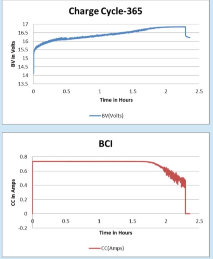
We're having an oscillation issue with the BQ24616. What makes this oscillation unusual is that it doesn't happen every cycle. We can cycle (charge and discharge) the charger multiple times with no problem, but then eventually one cycle will show an oscillation, and then the next cycle may be back to normal with no oscillation.
The primary issue is that this oscillation seems to be causing the charge cycle to terminate prematurely. When a charge cycle shows this oscillation, the charge voltage oscillates while in the current regulation phase, and then the charge current oscillates once in the voltage regulation phase. This doesn't make sense to me and I would think a stability issue would cause the charge current to oscillate when in the current regulation phase, and the charge voltage to oscillate when in the voltage regulation phase.
We're using Lo=6.8uH, and Co=20uF as recommended in the datasheet.
One thing we have a bit different is the value of the feedforward capacitor placed across the top resistor in the feedback resistor divider. In the datasheet the R2=500k, R1=100k, and Cff=22pF, so 500k || 100k = 83.3k giving an RC of 83.3k x 22pF = 1.83e-6. Whereas we have R2=165k, R1=24k, and Cff=22pF giving an RC of 20.95k x 22pF = 0.46e-6.
How critical is the RC time constant set by the feedforward cap? To match the RC in the datasheet we need to increase Cff by 4x. Any chance this difference could cause such an oscillation?
Attached is an image showing this oscillation and early charge termination. This is charge cycle #365 and the previous 364 charge cycles had no issue. The charge termination current is set to 152mA, but you can see the charge was terminated at about 400mA.
Any ideas? This issue is preventing us from releasing the product to market so I would really appreciate a prompt reply.
Thanks,
John Teel (former TI'er)

