This thread has been locked.

If you have a related question, please click the "Ask a related question" button in the top right corner. The newly created question will be automatically linked to this question.

TPS54525 dies after nearly 5 seconds

Other Parts Discussed in Thread: TPS54525

Well, firstly, forgive me for my bad english.

I have experienced an issue with TPS54525. 

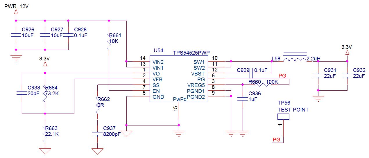
My system consists of a converter using TPS54525 with 12V input and 3.3V output connects to some PIRs, Op-Amp and 4 high-power IR LEDs. These IR LEDs, when on, will consume nearly 4A, so that's why I choosed TSP54525 for its 5.5A output. That system works fine with previos power comes from DSP system (before I added IR LEDs).

The schematic is mostly based on the recomment one in TPS54525 datasheet with proper resistors value for 3.3V output. EN pin ties to VIN through 10K pull-up resistor. 

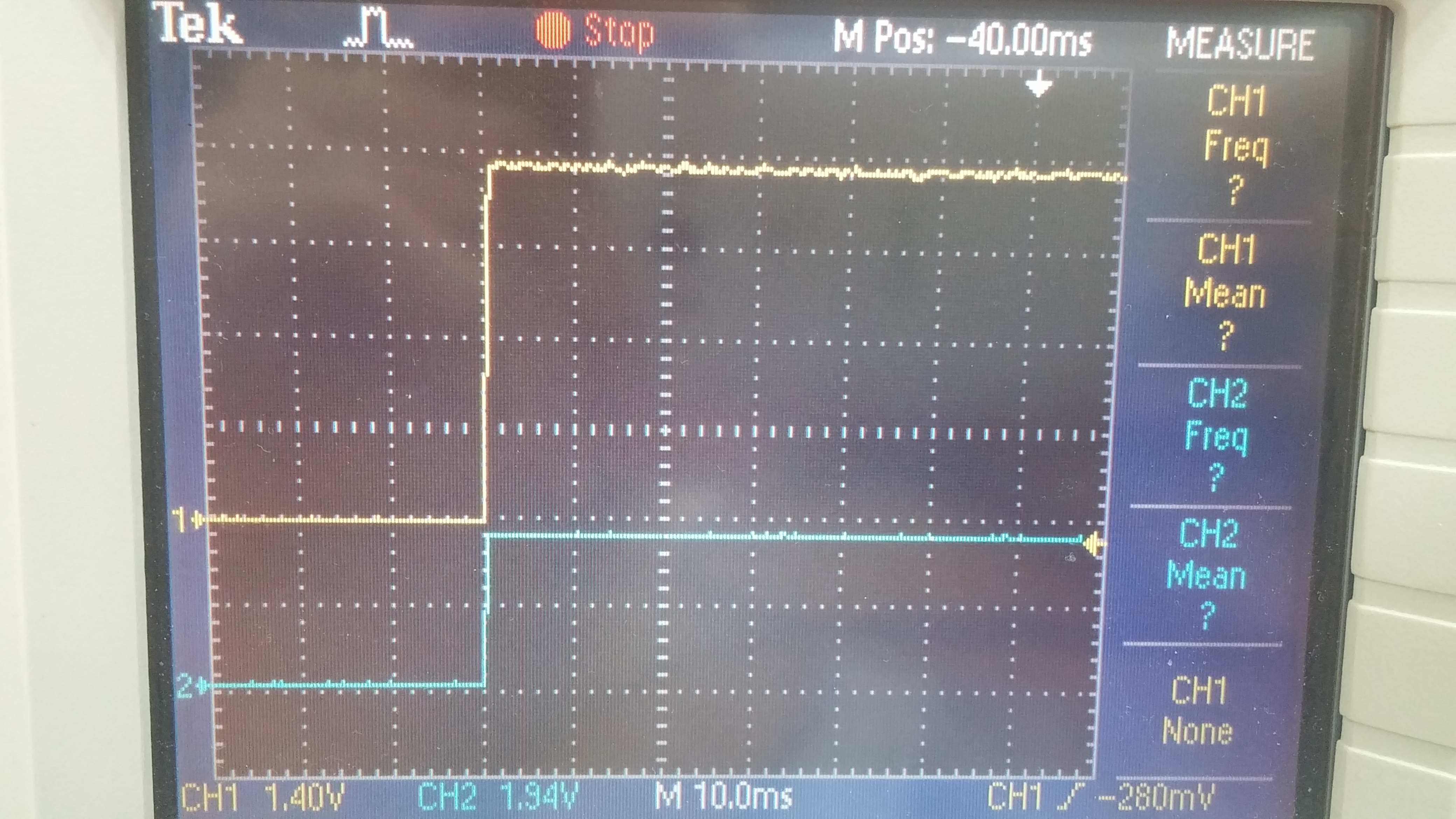
Normally, the system will only consume 0.01A ('cause IR LEDs usually off). But the problem is, when I connect 12V to the system, it eats up to 0.13A for about 5 secs, and then the converter just dies. VO and VREG5 = 0. I tried to disconnect IR LEDs but the problem still there. 

According to datasheet, it seems like I didn't trigger any protective functions. Any ideads how to solve this? 

Best regards,

Quang Dao

  • Is the part damaged? When you cycle the 12 V input does it try to re-start? Can you post a start up waveform including Vout and SW node?
  • JohnTucker said:
    Is the part damaged? When you cycle the 12 V input does it try to re-start? Can you post a start up waveform including Vout and SW node?

    I don't think the part damaged, I have 6 boards, and all of them have that problem.

    It does try to restart when I cycle the 12V input.

    Here is the startup waveform:

    1st channel is sampled after L58 - 3.3V

    2nd channel is sampled at PG output - 5.5V

    1st channel is sampled after VO pin - 3.3V

    2nd channel is sampled after SW1-2 pins and before L58.

    Is that because of the chosen components? According to the datasheet, some cap is recomment to be ceramic cap.

    Thanks for your help.

  • You can't really tell much at those time scales. What is the vertical scale per division?
  • To be honest, I mostly work on system software, and this is the first time I ever touch the oscilloscope. So sorry about previous waveforms.

    After a while playing with the oscilloscope, here is what I've got. I can't manage to capture the start sequence.

    For CH1 vertical pos is 0 divs, CH2 is -3 divs.

  • That looks like normal operation. I think you will need to trigger on the falling edge of the 3.3 V output and wait for it to trigger after 5 sec. of operation. I would use a time scale of maybe 5 usec/div. 2V and 5V/div are fine for vertical scale.
  • Thanks for your reply,

    I tried to capture the waveform falling edge of the 3.3V output, but as you can see in previos signal, it has a lot of noise. So it always trigger at somewhere in the middle of the operation time.

    Here is the best that I got.

    CH1 is PG output.

    CH1 is 3.3V output.

  • Your output voltage is rising up out of tolerance and triggering the OVP, which latches off the device. You will probably want to use 20 MHz BWL ans use a very short (< 1cm) ground lead to minimize the noise spikes. You will want to trigger on the output rising above 3.3V and zoom in no more than 5 usec / div. If you can capture the inductor current waveform that would be a plus. You will need a clamp on current probe and attach a wire loop in series with the inductor to do that.
  • I tried to use 20MHz BWL and shorten the ground lead but I just can't get rid of the noise spikes. My oscilloscope doesn't support Current probe, I tried to connect ground lead to 1 side, and probe on the other side of the inductor but the output wave seems ridiculous.

    Anyway, the problem is VO suddently goes high and triggers the OVP. Do you have any idea why it happens?
  • Usually it is 2 things:

    1.  Load transient going from high load current to light load current

    2.  Leakage form some other voltage rail pulling 3.3 V up.

    There are other possibilities, but those are most likely.

  • Thanks for your reply,

    So in this case, I think it's first reason. As I already mentioned, the board itself just consumes about 0.01A with normal operation (without IR LEDs), but it always comes up to 0.1A at 12V with this TPS54525. Something must consumes these 0.1A, but it isn't the OPAMP or PIRs, I'm so sure about it.

    Thanks for your help again, I will try to figure it out and fix it from now on.

    Quang Dao