This thread has been locked.

If you have a related question, please click the "Ask a related question" button in the top right corner. The newly created question will be automatically linked to this question.

BQ24251RGET does'n charge

Other Parts Discussed in Thread: BQ24251, BQ27421-G1, TPS63001, BQ24253

Hello,

I am using a bq24251 ic in a system which i will describe below (i know it is not recommended for new designs, but unfortunately this is what the costumer has/wants):

-The system is powered from a LiPo battery - kokam SLPB526495, with protection circuit (tried one without the protection circuit, same results)

- current consumptiopn is 20mA ( know it is overkill with a 3300mAh battery, but it will have a loooong standby)

-Charging is done with a dedicated charger (5V, 2,1A and D+ and D- shorted together). It will be necessary to work with a PC USB connection, too(5v, 500mA) but for the moment I will be happy to make it work with the dedicated charger.

-between the battery and Vbat pin of BQ24251 I use a BQ27421-G1 fuel gauge (i2c connected)

-board processor is STM32F405

-another i2c slave is a LCD MCCOG420005A6W

-BQ24251 Vsys is connected to one TPS63001 buck-boost to output 3,3V. (It has a 10u capacitor on input)

BQ24251 setup

- ILIM and VDPM shorted to ground

- ISET to GND with 180ohm resistor

- inductor used is 1uH COILCRAFT 1812PS-102JLC (farnell code 2287053, for more info)

- capacitor used as recommended by datasheet (22u on Vsys, 33n between BOOT and SW, 1u on PMID, 1u on LDO, 1u on VBAT)

- TS pin is 50% VLDO (divider made by to two 15k resistor on LDO to GND)

I have tried to start it in standalone mode, it didn't work. It doesn't start charging. So I went in host mode. After many iteration I got up to this:

- I connect the battery (3,8V)

- I write the registry with the following data 0x40 0x6C 0x8C 0xF8 0x00 0xA8 0xE0

- Once every 30 seconds I write the registry with the same data as above. I know it would be enough to write just de WD_EN from REG1 (adress0x00), but just to be sure...

- I wait 10 sec (just not to hurry things)

- I connect the charger

- I activate the DPDM_EN - B4 from REG 5 (address 0x04)

- I read the registry : 0x50 0xEC 0x8C 0xF8 0x10 0xA8 0xE0

- I wait a few seconds for de D+/D- detection to finish

- I read the registry again : 0x50 0xEC 0x8C 0xF8 0x00 0xA8 0xE0

Now it says it is in charging mode, but there is no current flowing into the battery. The load is powered only by the battery. Form the charger it is drown only 3mA.

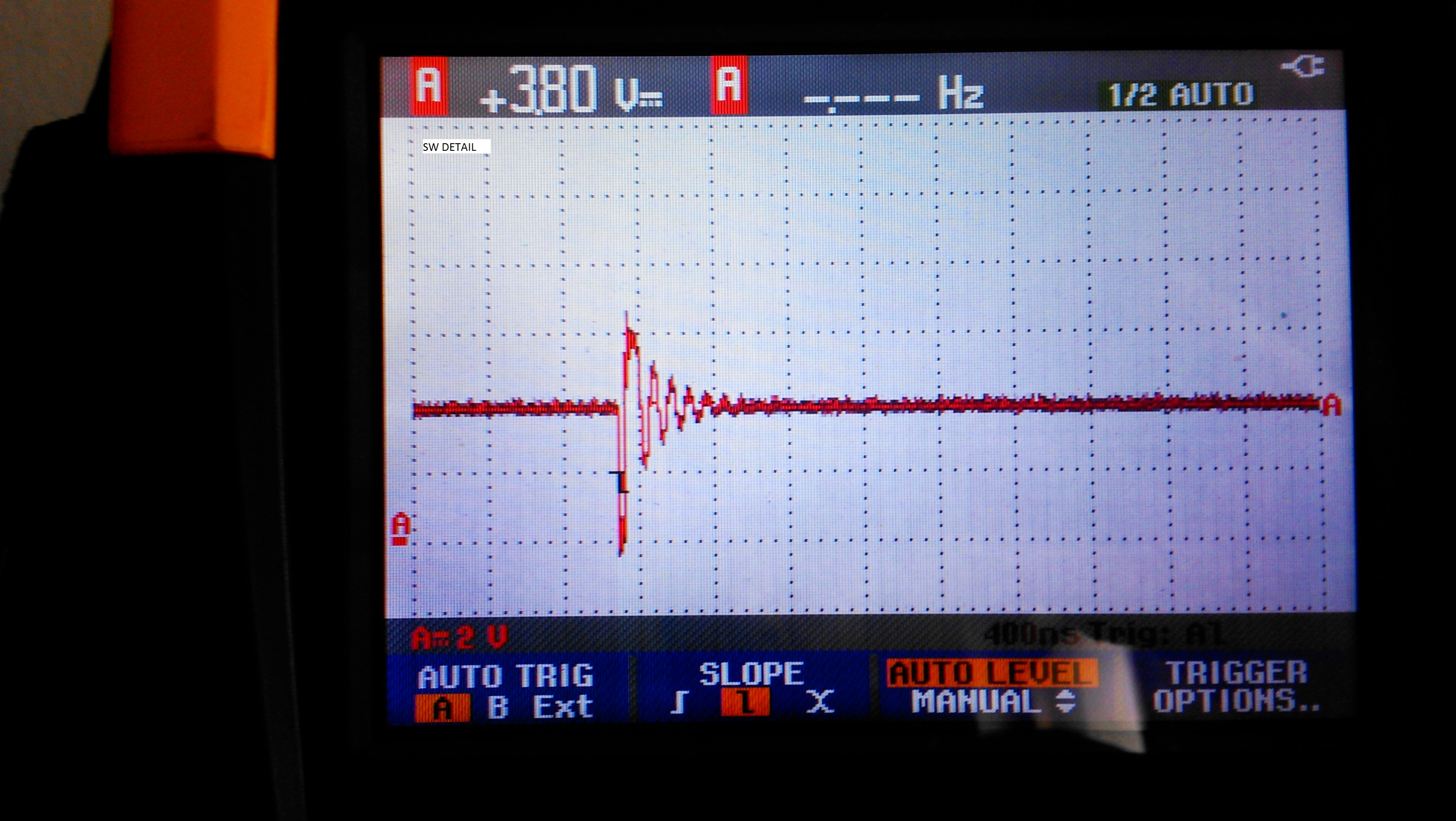
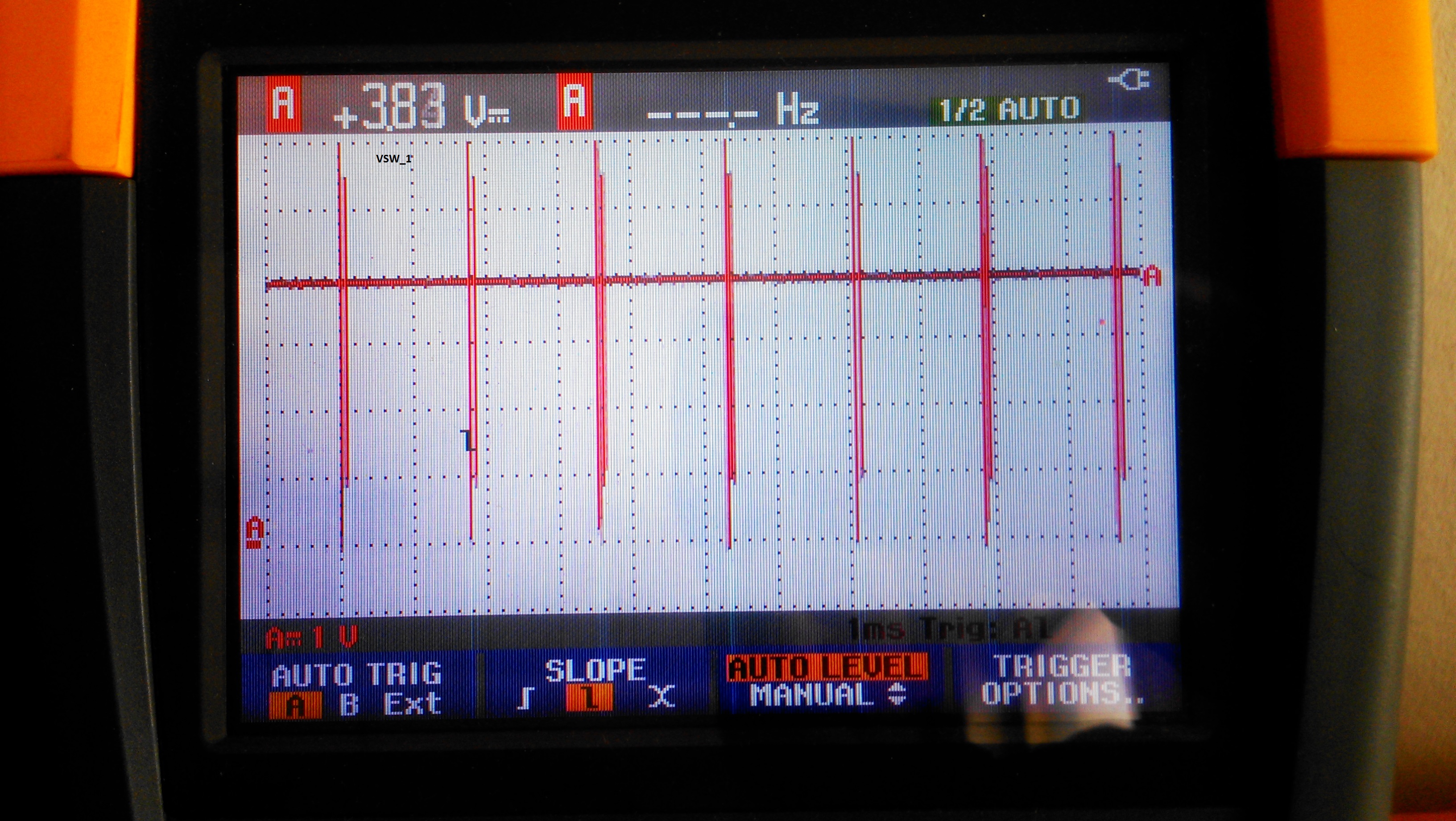
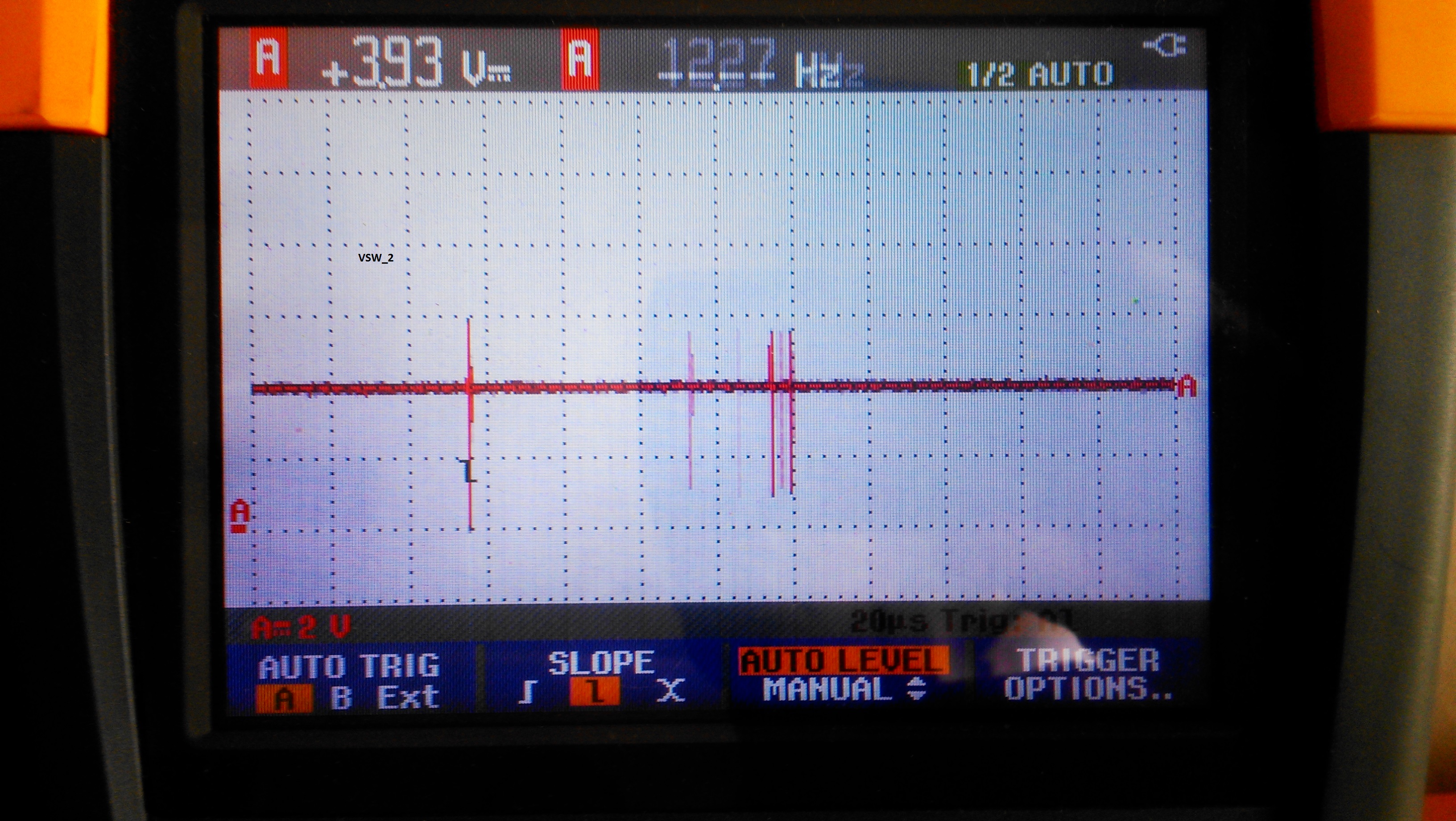
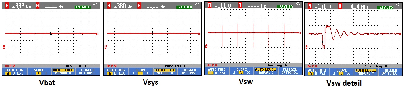
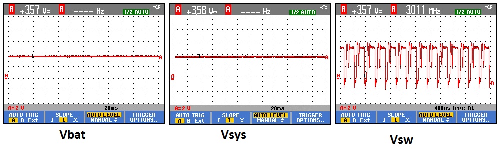
The SW pin folows the Vbat (it should be +100mV). It shows spikes with a frequency of 240-250 Hz, increasing sporadically to 500Hz.

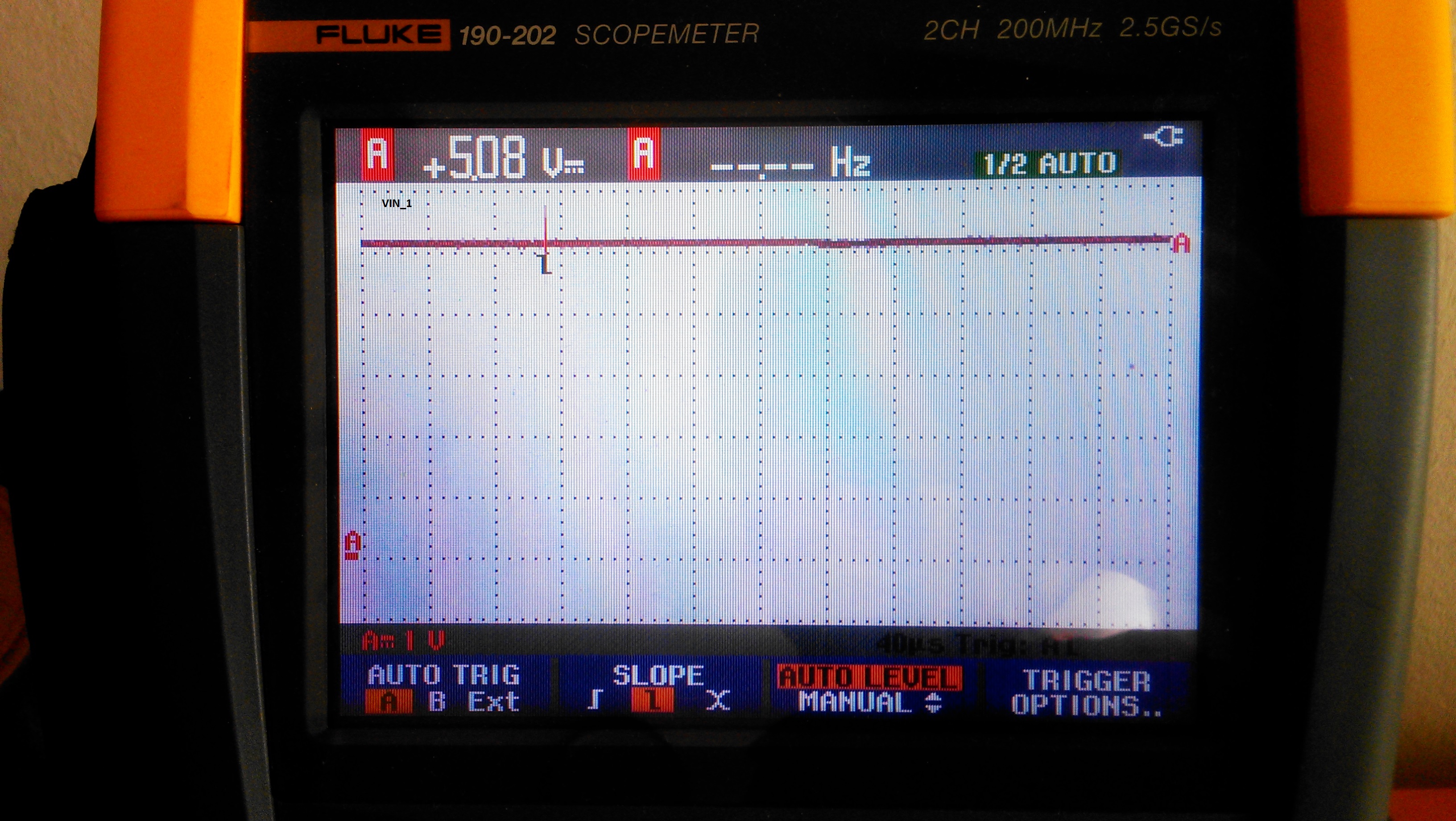
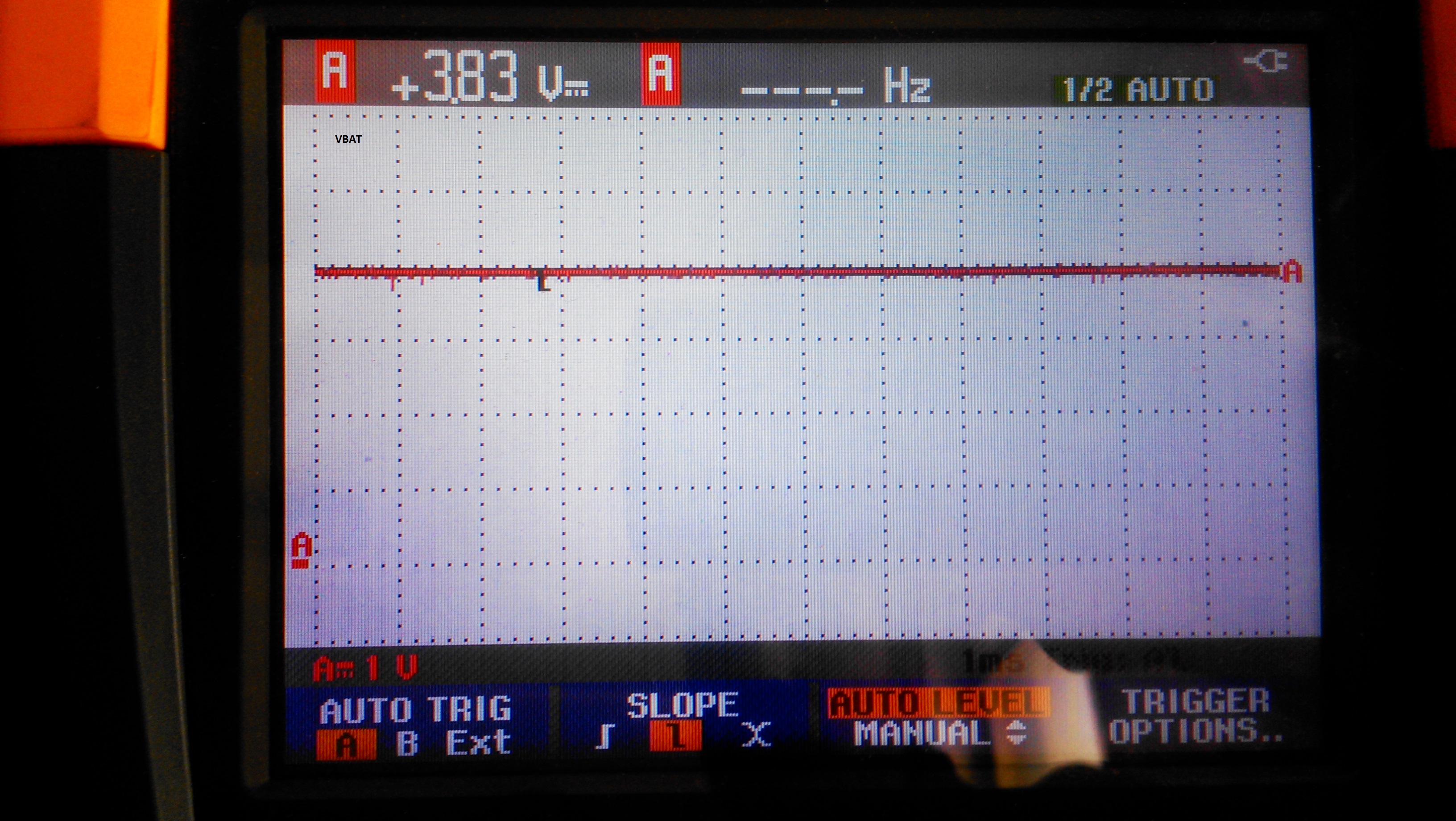
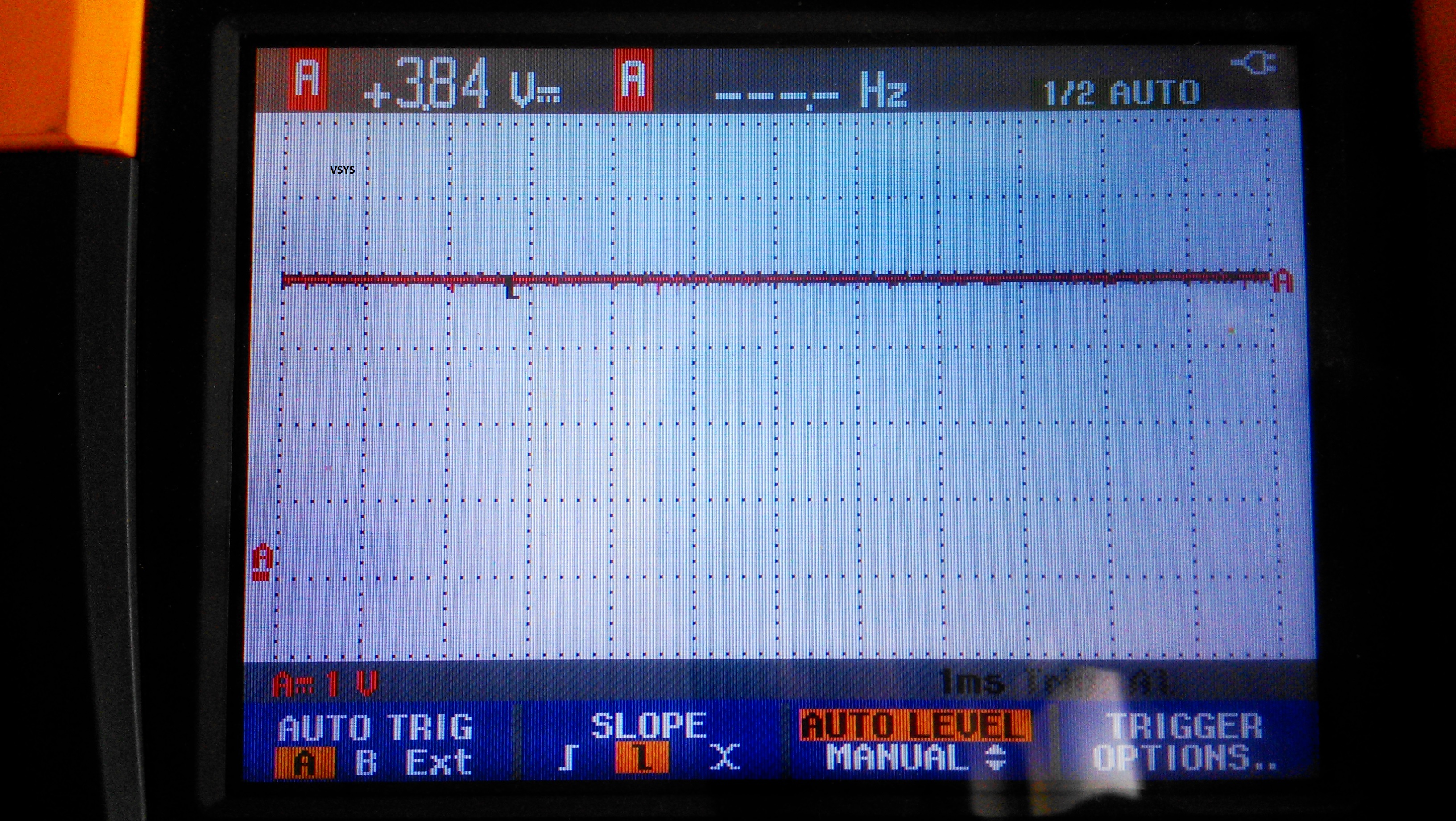
Vsys is equal to Vbat.

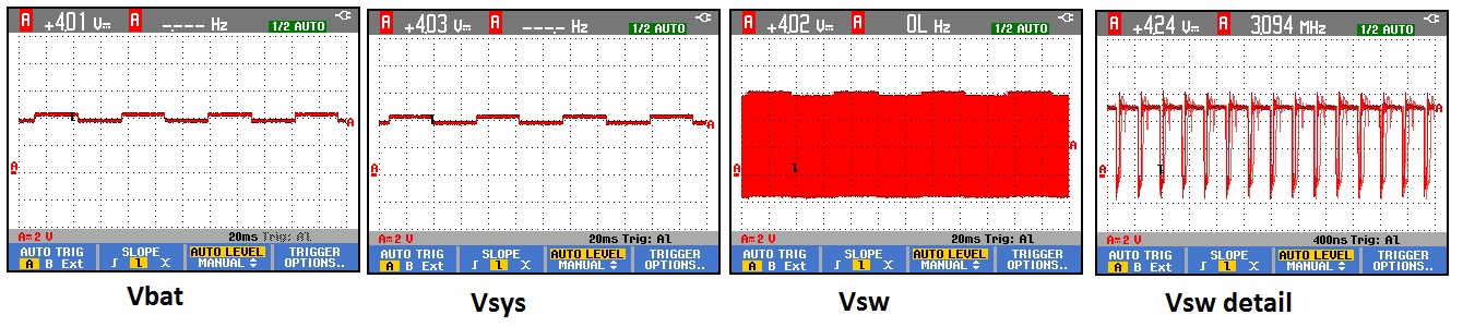
When the battery is more discharged (3,6V ), if I connect a load of aprox. 4 ohms, the consumption goes to almost 900mA. Then the charger start to kick in (freq on Vsw is 3MHz, now), and the 900mA are drown from the charger instead the battery. If I remove the load, the battery goes into charging with a little more than 1A.

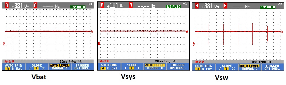
If the battery is 3,8V the charger never kicks in (maybe if the voltage drops below 3,5 -3,6 but I don't have the patience to wait that long, and besides it is not ok).

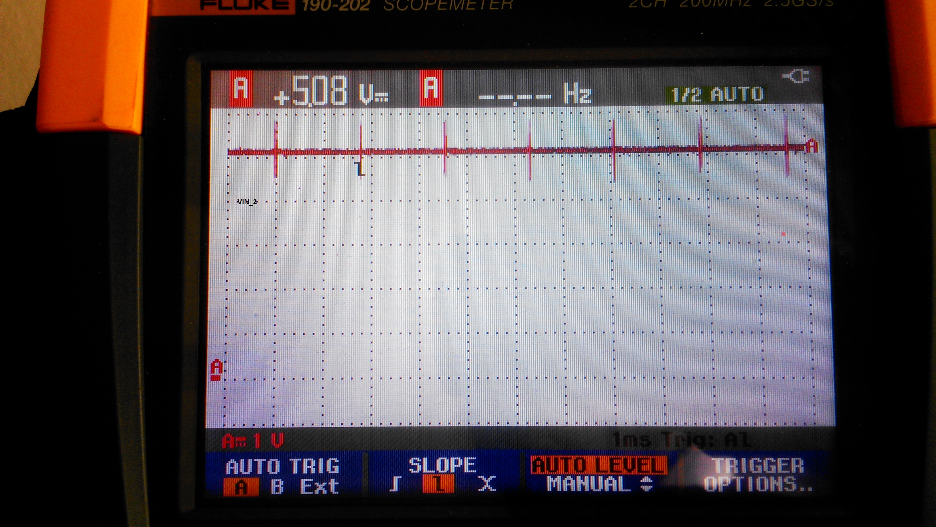
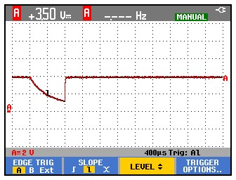
The Power Good pin is oscillating when the 5V IN is applied.

It seems like the actual charging is started only if the battery is below 3,5V, which is not good at all, and not as it say in the datasheet (the fig 15 and 16 shows a something else). The Vsys should be a little higher then Vbat (at least 30mV in BATREG and 100mV in SYSREG).

The bottom line, when I connect the 5V on Vin, PG pin is oscillating instead of going low (5V output does not have any ripple, does not goes low, nothing visible on oscilloscope, and can give a little more then 3A), the BQ24251 says it is in charging mode, but the actual charging never happens.

If anyone can help me with any idea, it would be great, because I ended all of mine. I checked the board and it does not have errors, it is done as it is said in the datasheet it should be. Maybe it is something obvious or I missed something int the datasheet, but now I am in a loop - checkin regs, writing regs, measuring board - so I am stuck

Thank you

  • HI Doru,
    could you please send me the schematic and also some useful waveforms (like the one on the SW pin)?
    Do you have the EVM? If so, have you tried replicating the issue?
    Thanks.

    Sergio
  • Hi Sergio,

    I am sorry for the long delay to respond, but the project was put on hold for a while and I didn't have access to the device. Now I am back, and I attached the schematic file and waveform from BAT, SYS and SW pins. I couldn't measure the frequency of the pulses on SW pin because it was highly variable.

    Also, the PG pin is oscilating when the 5V input is connected. Otherwise it stays at Vdd. The input is ok, it can give the power required by the charger (even if not, VDPM should kick in). I have tried also different power supplyes, phone and tablet chargers, the PG pin is not steady when IN is connected to 5V (also tried higher voltages).

    I don't have an EVM to replicate the issue, but again I don't know what the issue is. I have checked the board and it is OK, I tried both stand-alone mode and programmed from i2c and it works the same way.

    The IN pin is powered from a bench power supply 5,00V and 3A. The registers are read as 0x50 0xEC 0x 8C 0x CF 0x80 0x00 0x A8 0xE0 (charging and everything ok accordingly to datasheet) but there is no actually charging going on. The current drawn from the power supply is less then 10 mA, and the gauge meter shows 17mA being drawn from the battery.

    Again, I am sorry I didn't give any response for so long, it wasn't because I wasn't interested but I was caught with other projects and the only response I would have been able to give would have  been that I couldn't provide the schematics and waveforms.

    Thank you

  • Hello,

    Does anybody have any ideas about what I could do to make this BQ24251 to work, or at least what I might be doing wrong?

    I have checked all I could think off, so to me it looks like a bad IC lot. The only way to resolve that is to switch to an LTC4090 that I've worked with in the past, and it worked fine. But that means to redesign the schematics and PCB, I and would really like not to( time, money, being left whit a bunch of BQ24251 to be used  for decorating my desk).

    Thank you

  • Hi Doru,

    I read through your post, it seems to me the converter was working fine. As you discharged battery to < 3.5V, you start to see charge current. This is expected, however due to MINSYS regulation. converter will try to keep SYS at or above 3.5V.

    On the other hand, charger seems not able to detect the battery properly. The best way to debug it is to isolate the charger from other components. Can you remove the gauge from BAT pin and connect your battery directly to bq24251? If there is nothing connected at BAT, you should see alternating square waveforms at BAT, meaning, device is trying to find a battery(datasheet , 9.3.6, page 24). It will stop once battery is detected.

    The other possible cause is, Battery Regulation Voltage(Reg03, VBATREG, Bit2-7) was mistakenly set(or reset) to 3.5V(=0x00) instead of 4.2V, which is less likely according to your readings. But please double check by writing different values into this register and confirm response is expected. For example, if you set VBATREG=4V, it won't charge a 4.2V battery, but will do on a 3.8V battery. 

    Last but not least, did you see this on one board, or multiple boards?

    This device has been widely used by many customers. I am sure we can make your board work as well!

    Best Regards,

    Linhong

  • Hi,

    I will remove the gauge from the board and give it a try with the battery connected directly to the BAT pin. If there is no battery connected and only USB 5V there is a square waveform on BAT pin (centered on 4V, 0,5V amplitude).

    As for the registry value, I will check them again, but the software writes every 30 seconds the next values: 0x40 0x6C 0x8C 0xF8 0x 00 0xA8 0xE0. I will write different values, and check what happens.

    As for now, I am working with a single board (a prototype) but I have tried 2 IC and they act the same. I have checked the board 3 times and I gave it  to someone else too, in case I missed something. I couldn't find anything wrong.

    Thank you,

    Doru

  • Hi,
    I have connected the battery directly to the BAT pin, the connection between BAT and gauge being interrupted (cut the copper on PCB). It works exactly the same. It says it is charging, but actually it is drawing only 3mA from the IN input.
    I have tried to connect the IN directly on the power pack, not trough the protection circuitry, but with the same result.
    I tried with a mobile phone battery, without any protection circuit, just the same.

    I modified the firmware from STM, writing different values in Reg03, VBATREG, Bit2-7, and the response was always OK. On boot I write the registry with the desired values and after that, every 30 seconds I do a watchdog reset and write the registry again (it is overkill, but just to be safe).

    On the other hand, I have noticed something interesting and I can't figure out why. The scenario goes like that:
    - I connect the battery to the board
    - I read the status of the board, the BQ24251 regs, I display them on a LCD
    - I connect a power supply to the IN pin, with a modified microUSB cable, D+ shorted with D-. (5,1V, 3A max).
    - I read the regs, nothing happens, it says it is charging, but only 3mA is drawn from the power suply.
    - the PG pin is oscillating.
    - I start to decrease the voltage on IN input, from the power source.
    - When I get to 4,7V, PG pin goes low (with a 0,5mV noise) and it START CHARGING. I increase the voltage to 5,3V and 300mA are drawn from the power supply , 420mA being send to battery (3,87V), accordingly to the gauge.
    - I read the regs at 4,7V and I get 0x50 0xEC 0x8C 0xF8 !!!0x40!!! 0xA8 0xE0, the strange value being 0x40 which is VIN_DPM_ACTIVE. But why, since IN DPM THRESHOLD is set at 4,2V?
    - I have modified R5 to 0x06 to set IN DPM THRESHOLD to 4,68. It does just the same. Start charging when IN goes to 4,7, and keeps charging when I increase the voltage.
    - If I remove IN and connect again, still no charging (even if the regs says so). Decrease to 4,7, it starts.

    And another thing which I thought it is not related wit the issue at hand, but who knows. Ever since I got the BQ24251 in the I2C net (LCD, gauge, BQ24251), the communication hangs with SDA being kept low. I didn't have time to debug properly the issue, but what it is interesting is that it hangs sometimes when there is no i2c communication (I talk to one slave, is OK, I try to talk to the next one, SDA is down). I can exit from this only by removing the battery and the IN input. I don't want to blame it on the BQ24251, but this never happens if I don't talk to it (tried in stand alone mode - no i2c comm with it and also by physically cut off the SDA and SCL lines). I'll go further with the issue but first I want to fix the charging problem.

    Best Regards,
    Doru
  • Hi Doru,

    While we are debugging this problem, is it possible to try out on another board to confirm the problem is systematic? Or use an bq24251EVM to replace your board so that to confirm your PS, battery, and Gauge setup are ok? I'd like to make sure we are not debugging a random defect.

    With that said, Indeed, quite a few things you were seeing do not make sense. something seems wrong in the control/setup unit. We need to isolate them one by one:

    1. VINDPM. per your schematic, VDPM is shorted to GND. This will set VINDPM to 4.68V, which is close to 4.7V. So it makes sense to see VINDPM active, but it doesn't make sense to start charging at this point! Something has shut off the charger at the beginning.

    2. SDA. Pulling SDA down doesn't sound good. If I2C is not reliable and reset the device randomly, we won't get consistent result.

    3. MINSYS. together with VINDPM, it seems charger has to go regulation first, before starts to charge.

    Questions:

    A. what kind of power supply do you use? Does it have limit on startup(1 and 3)? have you tried a Keithley for example?

    B. I noticed you connected D+/D- as well. Does it go into an adapter? It sometimes may cause confusion.

    C. What's your battery voltage? when it charges, how high voltage it will charge to?

    Suggestions:

    Let us make the setup even much simpler:

    - VIN=5V(directly to PS, with 1A+ limit on current), BAT=3.8V(directly from battery or simulator), Nothing else.

    - remove all other active components from the circuit, including gauge(already done), protector, SYS load etc.

    - Keep SYS floating, SCL/SDA floating, D+/D- floating,

    - please list all other pin conditions that are not floating, but connected with something(resistor or cap). 

    In this setup, you should see 500mA charging current. If not, can you measure the voltage(and better with current) at VIN, BAT and SYS pin(at pin side, not the equipment side)? A Waveform at SW will be very helpful.

    Best Regards,

    Linhong

  • Hi,

    Regarding the use of another board for tests, it would be somewhat difficult and it may take some time. This board is a prototype, so I have to make another one, and some of the components will have to be de-soldered from the old one. If we can't figure it out what is wrong with this one, I might get to that.

    For the power supply I use a TENMA 72 6905. I tried with a dedicated charger (MWUSB3U from Farnell:2289557) and also on a PC USB port. All with the same result.

    The D+ D- pins were connected to a USB-UART adapter (CP2104). Now this adapter is cut off from the power line and from D+, D-. Those lines are only connected to BQ24251.

    The battery is a Kokam LiPo SLPB526495 - 4,2V and 3300mA. Now the battery is at 3,83V. If the protection circuit(overcurrent, undervoltage protection) is a problem I'll have to change the battery. The protection circuit comes from the producer embedded in the power pack, so cutting it out is not o solution. I will remove it on this one, to test the issue, but I hope this isn't it.

    I will make the recommended setup and be back with the results.

    Best regards,

    Doru

  • Hi,

    I have tested the setup suggested earlier, like this:

    - VIN, 5V from power supply, directly to VIN pin (no USB connector, soldered thick wire directly on board)

    - VBAT from battery directly to BAT pin

    - Load disconnected from VSYS

    - i2c floating (remove R9, R10) USB D+ D- floating (remove R45, R46)

    - Pins 1, 7, 8 (CE, STAT, PG) cut off from the processor (kept pull down on CE and pull up on STAT and PG)

    - All pins like in schematics:

      - TS at VLDO/2 with a divider (R17, R18 15K each)

      - ILIM shorted to GND

      - VDPM shorted to GND

      - all pins with recommended capacitors (1u VBAT, 22u SYS, 33n BOOT to SW, 1u PMID, 1u VLDO, 2.2u IN)

    I attached screens with VIN, VBAT, VSYS and VSW.

    The 0,01V difference between VBAT (3,83V) and VSYS(3,84) is actually caused by the fact that VBAT was somewhere between 3,83-3,84, and it was slowly switching between those two values. VSYS is following VBAT without any offset.

    Current drawn from IN was 3,67mA and from BAT was 0,06mA drawn from battery with IN connected and 0,01mA drawn from battery when IN is floating (strange). Any other currents are difficult to measure, because I have to remove components, solder them with wires so I can insert an ammeter, but I'll do it if necessary because I can't figure it out what is happening here.

    Thank you ,

    Doru

  • Hi Doru,

    It seems the charger/converter was not triggered to turn on. Battery is my top suspect. With this setup, can you try a few more things:

    1. If you add a load, say pulling 100mA out of SYS, what would be this current from? namely, how much from battery, how much from VIN? It should all from converter, and SW pin should show switching waveforms instead of pulses.

    2. Now remove battery, try #1 again. You should see similar thing, ie, converter should be on. Voltage may fluctuate, which is part of battery detection.

    3. If both 2 and 3 are ok, then battery was not detected properly. Do you have long cable to battery? Can you try a different type of battery without protector? or can you try a power supply that can sink current to simulate a battery? some protector coming with battery may falsely turnoff the battery,

    Best Regards,

    Linhong

  • Hi,

    I have done the new test, and here is what I got. (To begin with the end, it seems like a battery issue, but it also seems to be dependent on the current drawn from SYS):

    - I've put a resistive load on SYS - 24ohms

    First setup: NOKIA BP-5L phone battery (1500mAh,actual voltage 3,9V, as far as I know it doesn't have any protection circuit)

    - connect the battery to BAT - 150mA being drawn from battery

    - connect 5V to IN - nothing being drawn from IN

    - disconnect BAT, 90mA are drawn from IN

    - reconnect BAT - 150mA from BAT only

    - SW waveform doesn't show switching but pulses

    Second (and third )setup: Kokam battery (the one described above, second setup was without protection circuit, third with it , results were the same)

    - connect the battery to BAT - 150 mA are drawn from battery

    - connect 5V to IN - 200mA are drawn from IN, from which 42 are send to the battery

    - remove 5V from IN - 150mA from battery

    - reconnect 5V, remove battery - 160mA are drawn from IN

    - SW waveform looks like you said it should (switching freq at 3MHz)

    I have repeated the second and third setup connecting the battery to the gauge input. Result and values were the same as before (when connected to the IN pin).

    Faze 2: I have changed the load from 24 ohms to 47 ohms, tried all combination of battery with or without  protection and IN or gauge input:

    - connect the battery - 80mA are drawn from it

    - connect the 5V at IN - 80mA from BAT, nothing from IN, SW waveform with pulses(BAT at 3,72V and SYS pins at 3,7V)

    - remove battery - 60mA from IN, SW waveform is switching, 3MHz, SYS at 3,59V

    - reconnect battery - nothing from IN, 80mA from BAT, SW waveform with pulses

    If it is a battery detect issue, it seems it is somehow connected with the current being drawn from SYS (or the internal loop selection algorithm). Considering that my board is using 25mA max (usually below 10mA, and in stand by less then 1mA) that might be a killer issue.

    The battery cables are 10cm long and are pretty thick (can deliver 3,3A DC). The pack is delivered by the producer in a thermo - contractile wrap, with circuit board an wires (I have cut one open to remove the protector). I have tried the Nokia battery and weirdly it doesn't seems to be detected. I don't have any other batteries available, but I might get my hand on a 18650 Chinese soon.

    I think I'll have the PCB remade, and start with a clean one (I don't have any other ideas, and I have already checked all the component values, PCB lines, vias, etc). This one looks pretty messy after all that work done to it.

    Best Regards,

    Doru

  • Hi Doru,

    sorry for the later reply. I was out of office last week.

    Behavior in  your second case is expected one. With IN on, battery off, you should see square waveforms at both SYS and BAT. They two will follow each other. Can you capture the waveforms for both failing and passing cases? You can debug this according to datasheet 9.3.6, in page 24.

    Best Regards,

    Linhong

  • Hello,

    It took me some time to respond, but I've moved the bq24251 to a new board. I kept only the components in the dotted square, from the schematic attached earlier on the post. D+ and D- were left floating, SDA, SCL, STAT and PG pins were pulled up to Vsys with 10Kohms. As a load I used 47ohms resistor. The rest of the components were left as they were in the schematic. I repeated the test with batteries with and without protector, but the result were identical, so I will put only one set of waveforms. Tu sum it up:

    - battery with Vbatt = 3,83V

    - power source Vin = 5,00V, I=3A

    - load 47 ohms

    1. I connect the battery to BAT pin and the current drawn was 80mA. I didn't take snapshots of the waveform, they were all equal with the battery voltage (Vbat, Vsys, Vsw = 3,82V, no glitches, noise, etc).

    I connected the Vin. The current drawn from IN was 3mA, waveforms attached below.

    As as see it, there are no pulses on Vbat or Vsys, so the battery was detected (I guess in the step where Vbat was checked if it was smaller then 4,08V), but the charge didn't start. (when the processor was on the board, I never got battery error on registry when the battery was connected).

    2. I removed the battery. Current drawn from IN was 67mA, with the following waveforms:

    The ic doesn't detect the battery removal and it does not enter battery detection routine. If i connect the battery it goes back to step 1 waveforms.

    3. I disconnected the battery and 5V input. I reconnect the IN first, without the battery. This is what I've got

    Now it enters battery detection routine, but the interesting part is that the current consumption is 90mA (it was 67mA when I did connect the battery first) The current through the load is 80mA. So it looks like a very bad efficiency or some extra load inside the bq24251.

    4. I connect the battery, and now the current drawn from the IN is 3mA with the following waveforms:

    It seems like the battery is detected, but it is not charged. If I remove the battery all goes back to step 3, including the 90mA current consumption.

    Also, the PG pin doesn't work as expected (at least what I expected):

    - connect the battery, connect IN: PG is high. Remove the battery: PG still high

    - connect IN, without battery: PG is low. Connect the battery: PG goes high. Remove the battery: PG goes high (with pulses since is pulled up to Vsys).

    In my earlier post I said that at some point there was some charging happening, but I was wrong about it. What was happening was that the battery was connected to the system with an ammeter. The internal resistance messed up with the battery detection and when IN was connected, the pulses (4,2V and 3,7V) present on BAT and SYS pins did sent some current on the battery.

    Now all measurements were made with the battery connected directly to BAT pins. The current of 80mA drawn from the battery was measured at the beginning, with IN disconnected and verified by measuring the voltage across the 47ohms load.

    Every time I connect IN with the battery being connected, Vsys has a glitch like this:

    In the end, reviewing the diagram of AnyBoot Battery detection, it seems like the battery is actually detected. If the system starts from IN, and not from the battery it detects the battery removal too (but still no charging occurs).  When the battery is inserted first, The AnyBoot doesn't seem to work on battery removal. The battery voltage is 3,82V, so it should exit on Vbat < 4,08 condition. I assume there are some triggers for the AnyBoot algorithm to start: power on, In voltage presence, Bat voltage removal.

    Best regards,

    Doru

  • Hi Doru,

    How is your TS hooked up? Do you use NTC resistor? Is it attached to battery? Fault condition on TS will disable charging.

    This is really a strange problem. Have you tried to use a TI EVM with your battery, or system? Did that work? You can order an EVM from TI website.

    Regards,

    Linhong

  • Hi,

    I don't use a NTC. TS pin is connected on the middle of a divider, made of two 15Kohm resistors, connected between Vldo and GND (as shown on the schematic, I didn't change that). Vldo = 4,97V, voltage on TS pin is 2,47V.

    Regarding the EVM, I see what I can do, but I don't think my boss will buy one. I only need a small batch of this product, and the cost of EVM (even if it's not high) it almost as high as the cost for all the bq24xx ic.

    If it is not an issue with the bq24251 itself (faulty lot, fake or something) it must be something wrong with the board, the components used or the battery. The board I triple checked, and I have moved to a new board, the components used were all checked for values, so I don't know about that. I have checked with other brand of batteries, still the same.

    As a quick check, I will get these days a bq24253, and replace the old 24251, to see what happens.

    Thank you

    Doru

  • Hi  Doru,

    if EVM is not an option, are you able to find a power supply (like keithley 2420 etc that can sink current) to simulate a battery?

    If you used fixed value for TS, then it is not a problem. As I recall from your previous post, there was NO fault reported by charger.

    To swap the IC will definitely give us more clues.

    Best Regards,

    Linhong 

  • Hi,

    I've got the new bq24253, I've checked the board, components (again) and solder it. And, epic fail.

    It draws 150maA from IN, 100 to load, 50 goes into  battery (it is not in Weak or dead battery, IN current is 150mA, D+ and D- shorted, EN1 EN2 put to GND with 10Kohms). It does not react to EN1, EN2 change, Vsys shows 1V amplitude pulses. Removing the battery does not start battery detection algorithm, and there is no swithing waveform on Vsw. With no battery the Vsys is 4,7V. That lead me to the discovery of a short between SW pin and PMID. It is not the diodes inside the ic, it is a real short circuit. It might be some damage from soldering (it is present on the ic pins after removing it from the board).

    So, after all that I declare it a dead end with bqxx and will switch to something I used to work with. Not so smart, but after all smart doesn't seem to work for me.

    I am already too late with the project and I have spend too much time with something that should be only 1% of it.

    Thank you,

    Doru