This thread has been locked.

If you have a related question, please click the "Ask a related question" button in the top right corner. The newly created question will be automatically linked to this question.

TPS63000 Getting hot and consuming a lot more power, but still working

Other Parts Discussed in Thread: TPS63000, TPS61200

In an application for a servo amplifier, we are using the TPS63000 to create 5Vdc out of a 3.5Vdc supply. On our proto board the circuit worked fine, also some of the series production boards work fine. But it seems that on 40% of the series production boards the TPS63000 gets defective. Most of the time, this hapens when powering up the board. The TPS63000 then consumes a lot more power and gets very hot. The strang thing is that the TPS63000 just keeps working!

The flyback converter that feeds this circuit can not deliver the amount of power needed by the defective TPS63000, so that' why the board does not function correct. But when supplied with a seperate powersupply (that is also the way the board is tested at our test department), the board works fine (but still, the TPS63000 gets hot).

Does someone have an idea how it is possible that the TPS63000 gets defect, but still maintains its output voltage? I know the inductance of the inductor is marginal. But is it possible that the TPS63000 gets defective due to saturation of the inductor? The TPS63000 has a current sensing and limiting, so I assume the current is limited in that case. Also, when an internal FET dies, the TPS63000 stops working, but that is not the case.

Some details about the circuit:

The circuit is just like figure 19 in the datasheet with:
C1 = 100uF tantalum + 1uF ceramic
C2 = 2 x 220uF tantalum + 1uF ceramic + 100n ceramic + 10n ceramic
C3 = 100n ceramic
L1 = 3.3uH, 1.4A (Coilcraft 1812PS-332M)
R1 = 1.54Meg (+ 1.5pF parallel connected)
R2 = 165K
R3 = 100 Ohms

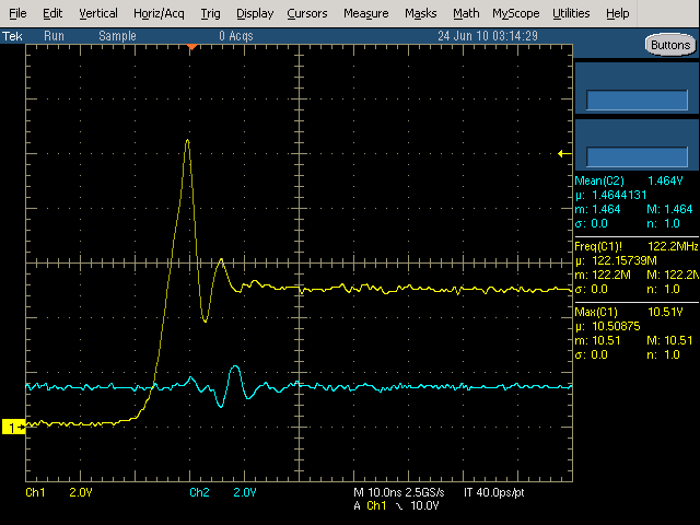
The input voltage is equal to 3.5Vdc, but there is a pi-filter connected between the flyback-converter and the TPS63000 circuit. Measurements showed that there is a little overshoot when turining on, but the voltage does not exceed 4 Volts, which far below the maximum operating input voltage.
The maximum load at the 5.17Vdc output is 300mA

I hope someone can tell me what is the cause of the problem.

Many thanks in advance!

  • Please read through the applications section in the datasheet, beginning on page 14.  There are several issues that could cause strange behavior:

    1. Component selection.  The TPS63000 is designed for use with ceramic capacitors.  Specifically, it requires on input capacitor of at least 4.7uF of ceramic.  Tantalum capacitors have a higher impedance, so 4.7uF of ceramic needs to be used.  Extra tantalum in parallel on the input will not hurt, but there must be 4.7uF of ceramic.  Likewise, the output capacitor needs to be a ceramic for control loop stability.  Please see equation 7 for the recommended capacitor value for stability.

    2. Layout.  Please check your layout versus the EVM layout, paying close attention to the placement of the output capacitor.

    In addition, if you just need to boost (and not buck) from 3.5V to 5.17V at 300 mA, the TPS61200 may be a better fit.

  • Dear Chris,

    Thank you for your response.

    I have done some measuring at the inductor and it showed out that during start-up a peak-voltage of more than 10V can be measured (see scope picture: CH1 is L2 connection, CH2 is L1 connection). This voltage spike is only a nanosecond long and I know the probe of the oscilloscope also contributes to this spike (when I put a second probe on the same measuring point, the spike is higher).

    But I have desoldered the 10uF/6.3V ceramic capacitors of the EVM board and I have soldered them right between the input terminal of the TPS63000 and its powerpad and between the ouput terminal of the TPS63000 and its powerpad. Unfortunately the voltage spike did not get any lower.
    Then, I also changed the 3.3uH 1.4A inductor to a 4.7uH 5.5A inductor, because I knew the inductor was marginal. But, unfortunately this also did not decrease the voltage spike.

    As long as the TPS63000 does not fail, we do not have stability problems, nor EMC problems. The datasheet gives a warning that an improper layout can lead to this problems, but we don' have these problems.

    So, at this point I don't  know what else to do. Is (during startup) a voltage spike of 10V (during 1 nanonsecond) lethal for the TPS63000, or is it just normal for an output voltage of 5Vdc?

    Changing the complete layout, and/or moving to an other DC/DC converter chip is not an option, because of the number of expensive boards already produced at this moment.

    I hope you can giver some more hints.

  • Hello Klaas

    I can assist you with this problem and will contact you through email.


    Bill