This thread has been locked.

If you have a related question, please click the "Ask a related question" button in the top right corner. The newly created question will be automatically linked to this question.

BQ24616 no charge activity with battery attached

Other Parts Discussed in Thread: BQ24616, BQ77PL900

Hello, I'm facing a strange BQ24616 behavior when trying to charge li-ion cell pack.

The setup:

  1. 6 series li-ion cells with build-in protection - new, precharged to ~3.7V.
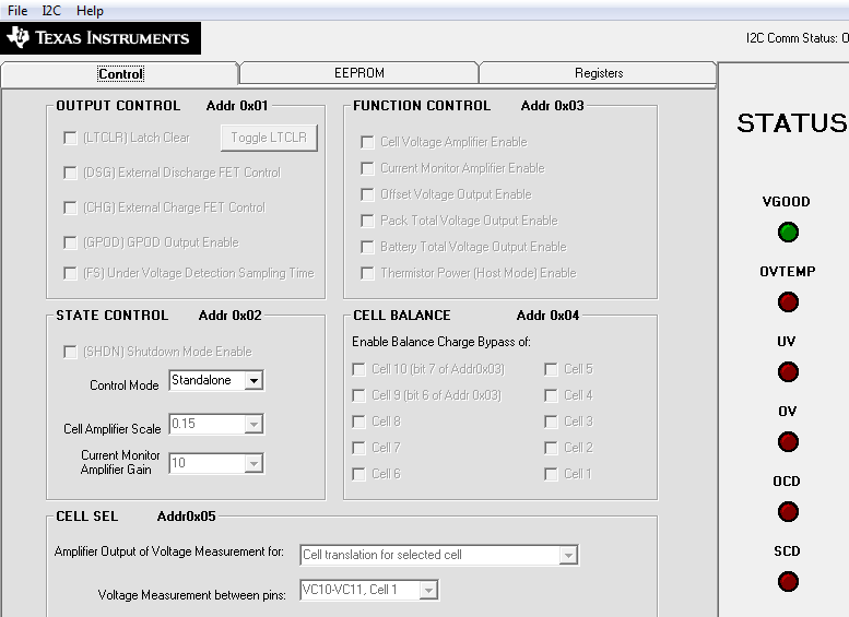
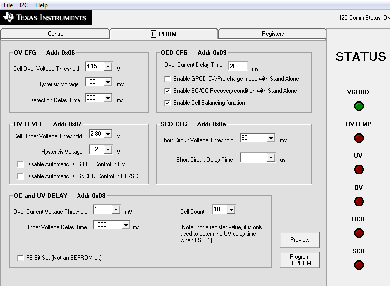
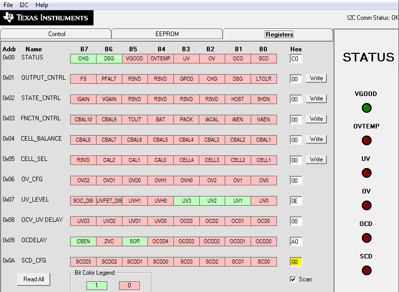
  2. BQ77PL900 AFE for ballancing (with external ballancing FETS) - tested with EV2300 (CHG and DSG FETS are working, IC is working)
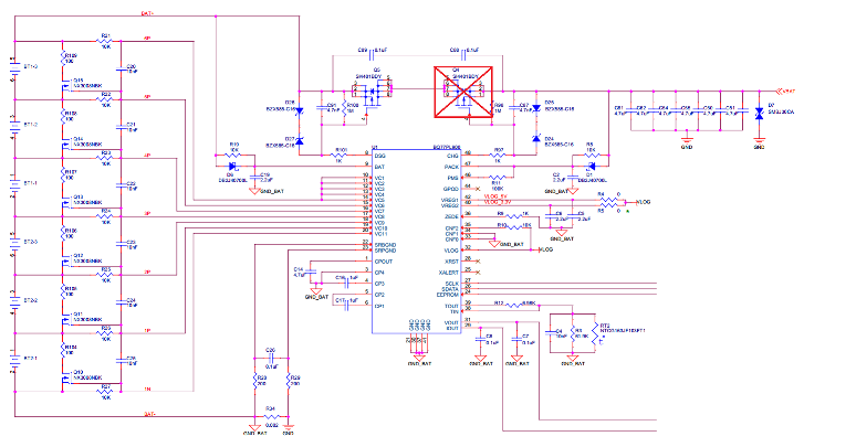
  3. BQ24616 with a basic circuit - ISET1=1.5A, ISET2=65mA (will be cutted to 125mA - OK), ACSET=3A, VCRHG=24.6V (4.1x6), System Load < 100mA
  4. External power - 28V regulated lab power unit

All cells are in place, BQ77PL900 is active. When turning on the external power or toggling CE there is no activity on PH, HIDRV, LODRV, however:

  1. nPG is low which means that BQ24616 passes power test, VCC=28.2V
  2. STAT1 and STAT2 are off (hi-z)
  3. VFB=1.86V, VBAT=21.9V
  4. VREF=3.3V, REGN=6V
  5. TS = 2.02V
  6. LODRV=0v, HIDRV=21v
  7. ISET1=300mV, ISET2=65mV, ACSET=610mV - as expected
  8. nBATDRV is also working: when AC on nBATDRV=28V, when AC off - nBATDRV=16V

What tests were done:

  1. Tried to short AC sense resistor - no change (after toggling CE)
  2. Tried to short TTC cap - no change (after toggling CE)
  3. Tried to short CHG and DSG FETS of BQ77PL900 - no change
  4. Tried to discharge cells - VBAT dropped from 21.9V to 20.8V - no change (after toggling CE)
  5. Tested charger PCB against shorts and line breaks - no problems detected

Then I've replaced each cell with a 180 Ohm resistor:

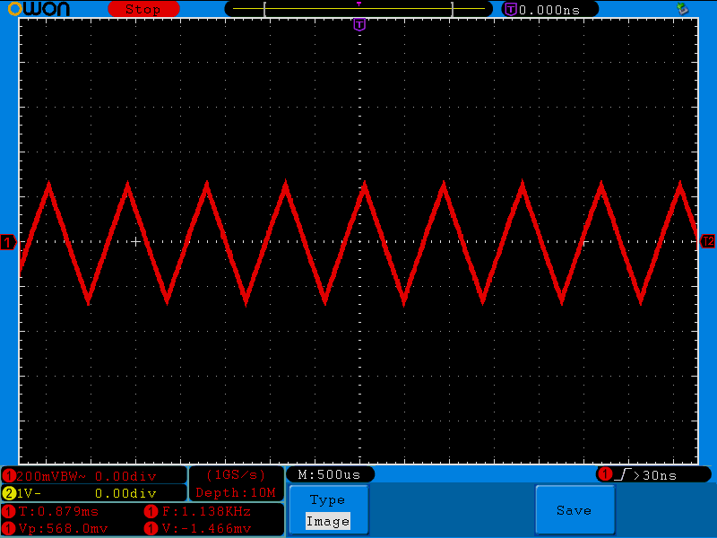
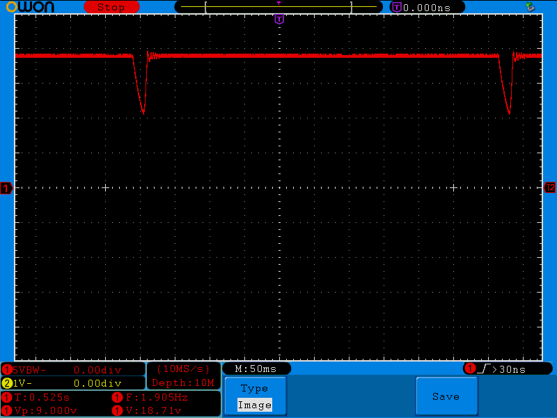
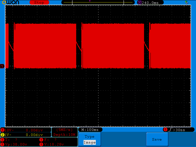
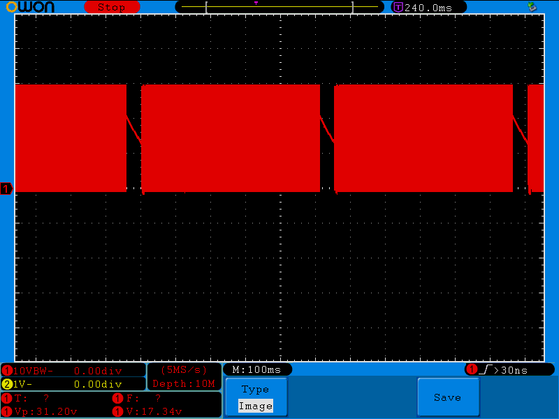
The BQ24616 started to work: HIDRV was toggling fast, PH was toggling also, on VBAT there was a ramp repeating each ~160ms (can't attach osc pictures now). STAT1 and STAT2 were OFF. Tried to short PTC to gnd and after CE toggle the BQ4616 stopped working as expected. 

So I gently assume that BQ24616 logic and charger circuit are working and components are pretty alive.

But what stops BQ24616 when I try to charge a pack in place?

  • Hi Konstantin,

    I will dig a bit deeper into the issue, and I will get back to you.

  • Konstantin,

    I am not familiar with AFE's, so we may have to dig deeper into that yet.

    However, could you expand more on the built in protection? That may be causing the BQ24616 to not detect the battery. One thing you can do is probe at the SRN node to see if there is a voltage there. The build in protection information should be in the batteries data sheet.

    Also, is the VFB voltage a steady 1.86 V with the cells in place? Or are there oscillations?

    This is probably unlikely, but what resistors are you using to set the Thermistor Sense Thresholds?
  • David,

    I'll be out of the office a week and a half. So I can do the tests after this time, however previously collected data and project info are with me.

    1) Li-ion cell is KeepPower P1835J (www.keeppower.com.cn/products_detail.php - i will try to find info on protection circuit inside (also i can try to do tests with unprotected cells)

    2) Voltages on FB and SRN nodes were steady without any oscillations

    The schematics for afe and charger are:

  • Konstantin,

    Once you run those tests, please let me know how they go. There are a couple other things I can suggest:

    It looks like you have your cells configured correctly in the AFE. However, could you double check the bits of the registers on the chip? From what I see so far, your hardware looks correctly set up. It may be more of a software issue.

    Could you also measure VCC and the SRN voltage with the battery pack in place? Depending on how lossy the FETs and Inductor are, the chip may be entering sleep mode (which would also explain the STAT1 and STAT2 LED's being off).

    Safe travels!
  • David,

    I.ve made tests using cells with no protection (NCR18650B). Still no charging.

    Voltages on core nodes are:

    1. VBAT = 21.71V
    2. VFB=1.85V
    3. VCC=28.08V
    4. VEXT(ADAPTER)=28.11V
    5. ACN=28.11V
    6. SRN=21.71V
    7. VREF=3.3V
    8. REGN=0.9V (CE=0), 6V(CE=1)
    9. TTC=0 (CE=0), when CE=1 there is a ramp with DC level of ~560mV, AC wfm in attach
    10. TS=2V
    11. BTST=21.33V
    12. PH=21.71V
    13. HIDRV=21.47V, LODRV=0V

    CE is toggling correctly, nPG is toggling correctly, no current limit on lab power supply. AFE registers are in attach.

    Still no changes on HIDRV, LODRV and PH when toggling CE or EXT power. I've found no excessive noise on charger analog inputs (at least no more than noise data with oscilloscope inputs shorted to pcb ground).

  • Also here are the waveforms when all cells are replaced with 180Ohm resistors:

    LODRV:

    HIDRV:

    BAT:

  • Konstantin,

    Thank you for the info. Could you also please attach waveforms of the BAT, HIDRIVE, and LODRIVE waveforms when the battery is attached? If possible, the PH node waveform would also be helpful.

  • Hello,

    Cause the batteries on my pcb are located at holders i've made a test with 5 cells inserted and the 6'th (topmost) not. The cell balancing function is turned on at AFE.

    I do not have jumpers on board, so the last what i can do is to desolder the DSG and CHG fets effectively isolating cells with a parto of AFE from rest of the circuit and connect another pack directly to charger.

    With 5 cells and external power on the waveforms are pretty much the same as in case with 180 Ohm resistors. When I insert the 6'th cell any charger activity stops instantly. The last wfm illustrates VFB voltage during insertion:

    5 CELLS HIDRV:

    5 CELLS PH:

    5 CELLS VBAT:

    5 CELLS VFB:

    6'th CELL INSERT VFB:

  • Konstantin,

    This issue is probably more related to the gauge and less with the charger. The gauge is somehow disconnecting the battery from the charger and the charger cannot continue charging because it cannot detect the battery. This waveform on the BAT is consistent with the waveform for battery detection, which means the battery is "absent". Please post in the gauge forum to get their opinion on the issue.

    Regards,

    Steven

  • Hello, Steven

    It's not an AFE BQ77PL900 issue. To partly prove it I've removed CHG  FET and connected battery pack directly to charger output. Still no normal charging.

    With removed battery pack system works as I previously wrote. With batteries in place from the cold start it shows STAT2=0 (wich means charging complete), however the pack voltage is low 20.8V vs expected 25.2V fully charged. If I toggle CE the system will show STAT2=STAT1=hiz as previously seen with AFE. Subsequent system starts with POR will give the results as previously seen with AFE.

    Still my PCB gives magical results.

  • Konstantin,

    Do you have a sourcemeter you can use, or maybe an electronic load with CV mode? You can set the sourcemeter/e-load to constant voltage mode to 22V and add 100uF cap to VBAT. Remove the AFE completely, we just want the charger to operate with nothing else that could affect the operation. The charger should be able to "detect" the sourcemeter and start charging.

    Regards,
    Steven
  • Hello,
    After all i've decided to change BQ24616. Asked PCB assembler who did the work to desolder an IC.
    So we found the defect - an assembly one (You can clearly see it on image). Visually on board this wasn't seen at all until IC removal.

    After soldering IC back correctly the charger started to work (with AFE). 

    Thanks for time spent!

    Regards,

    Konstantin.