This thread has been locked.

If you have a related question, please click the "Ask a related question" button in the top right corner. The newly created question will be automatically linked to this question.

Constant Current Source for Electrolysis

Other Parts Discussed in Thread: TPS54160, TPS40211EVM-352, TPS40211, DRV8412, TPS5420, TPS5430, TMS320F28027, TPS55383, TPS40200, TPS51020

Hello friends,

                     I am working on an application which works some what on the principle of Electrolysis. I have 2 electrodes (aluminium and copper) which are placed inside a metal box containing salty and impure sea water. Both the rods are applied +ve voltage and the body of the metal box is grounded ( in this electrolysis the current is actually flowing from the electrodes to the metal container) and some impurity is getting deposited on the aluminium rod. Now i have a very old and bulky system which has a Constant Current source from 0 to 1A, which can be controlled with a potentiometer.But the system is very bulky as it uses transformers and heat sink mounted transistors, but i have a feeling that with the revolution in semiconductor electronics the system can be reduced to a single board with some really small IC's like the TPS or something like that. TPS is a great league of black magicians, its unbeleiveable what this IC can do in such a small size, but most of the documents and application of TI websites explains it as a voltage regulator, but i guess it can also be used as a Constant Current Source over a range of 0-1A. Can some one plz provide some help about how to design it.

  •  

    An HB LED driver is a constant current source.   The links below are to an application note and evm using a switching regulator as an LED driver


    Using the TPS54160 as a High-Brightness LED Driver

    http://focus.ti.com/general/docs/litabsmultiplefilelist.tsp?literatureNumber=slva374


    Evaluation Module for a High-Brightness LED Driver using the TPS54160

    http://focus.ti.com/docs/toolsw/folders/print/tps54160evm-535.html


  • There is a higher voltage / higher current constant current source system also available.  The TPS40211EVM-352

    http://focus.ti.com/docs/toolsw/folders/print/tps40211evm-352.html

    The TPS40211 controller is implimented as a boost converter with external MOSFET.  The output current is forced through a ground resistor to generate a feedback voltage to produce a regulated current.  While the EVM does not impliment a potetiometer to control the current, this functionality is possible with an external POT and some minor soldering.


    The EVM is configured for a 42V open-circuit protection (don't know if this is too low for your application or not) and 700mA fixed current.

    SLUU351 (the User's Guide) details the schematic and PCB http://focus.ti.com/general/docs/litabsmultiplefilelist.tsp?literatureNumber=sluu351

    R3 is 30.1kOhms and R4 is Open, this sets the voltage drop on the current sense resistor (R13) to 260mV (TPS40211 reference voltage) which forced 700mV between the output terminals.  To increase this set point current to 1A, you will need to populate R4 with a 78.7kOhm resistor, which will force 3.3uA through R3 to maintain 260mV at the feedback pin.  This will increase the voltage drop across R13 to 360mV and drive 1A of current.

    To reduce the current to 0A, you will need to add a potetiometer from BP (approximately 8V) to GND with the wiper connected to the FB pin (Junction between R3 and R4) .  Zero current will be achieved when the current from the potetiometer supports 0.260V at the FB pin with zero volts across the current sense resistor.  This will require only 12uA of current, so you may want to place a 500kOhm resistor between the Potetiometer and the BP pin to increase the resolution of of the potetiometer.

    Alternately, you could replace the existing resistors with scaled resistors, changing R3 to 3.01kOhms and R4 to 7.87kOhms and reducing the series resistor value to 50kOhms, but you will also have to scale the feedback components R5, C2 and C3 by the same factor (decreasing R5 to 1.43kOhms and increasing C2 and C3 to 1000pF and 10nF respectively for the prior example)

    The potetiometer will allow you to adjust the current between 0A and 1A (it will be possible to increase above 1A as well)

    If you need more than 42V to force 1A through the electrolyte solution, you'll need to change the zener diode D3, which provides open-circuit protection to limit the ouptut voltage to 42V.

    If you need more than 50V at the ouptut, I would recommend changing Q2 to a higher voltage MOSFET as this MOSFET is only rated for 60V and it sees Vout + Vfd plus a small amount of ringing on the switching node.  The power diode D2 and output capacitors are rated for 100V.  If you need an output voltage greater than 100V, you will need to perform a full design using the schematic of the TPS40211EVM-352 as a reference.

  •  

    Thank U Mr. Miller & David,

                                         That was as good as the anatomy of the TPS40211 , thats Gr8, i hope i will also be able to understand things in electronics that deeply. I will try that solution. Also recently i was just browsing through other TI products, thats when i came across the DRV9812, it seems that it just the thing i was searching for, it has 4 four O/P channels, each can be controlled via a dedicated PWM. In my application also i need to control the current through 2 pairs of alu- Cu  rods. But the DRV9812 is still is the PREVIEW status it is not commercially available, any idea by when will it be made available online.


  • I will see what I can find out about the expected release date of the DRV9812 and DRV9822 devices.


    What conduction voltage (output) does this process require?

  •  

    The older system which i have, has a voltage selector switch on the front panel with voltages of 6v,12v,18v and 24v, but in modern systems, there is no option for voltage selection, they have 4 displays showing the current through each electrode, and swicthes to control that current, in these systems the voltage is kept at a default value of 24V.  While observing the operation of the system i have noticed that it simply works like a standard DC power supply used in a laboratory.

    For e.g. If the voltage is set at 24v

    The voltage measured between any of the electrode and metal container when the electrode is not dipped in the salty water(electrolyte) = 24V

    As soon as i dip the electrode in the water this volatge trips to some 1.2V and maximum  current starts to flow depending on the current limit which is set.

  • So, what you need at the output terminals is approximately 1.2V @ upto 1A?


    A boot converter such as the TPS40211 will not work properly in this application as the ouptut voltage is less than the input voltage.  You'll need a BUCK type converter instead.  I am still checking on the expected release of the DRV9812 and DRV9822 devices

  • Muhammad

    The DRV9812 is not planned to be released in the near future. Also the DRV9812 is only a driver, there is no regulation loop build in - it all needs to be done externally. So the TPS40xxx parts are more suitable as they have a feedback loop.

    If you still think the DRV9812 type of parts are what the application needs, i can recomend to look at the DRV8412 - this part have siminar functionality and is released and available in our sample program.

    best regards

    Kim Nordtorp Madsen

  • Kim

           I was thinking of  the DRV9812 as a possible solution because in the TI - LED reference design cookbook  it has been illustrated as a Constant Current Source for LED.


    Peter

              Oh yes you are right that wont work. I had already done a lot of the designing, all in vane.

    Output requirement is not exactly 1.2V.      See i will explain my observations. When i am setting the system for 24V o/p and i limit the current selection knob for say 1A (maximum setting), i am getting the 24v at the o/p when the electrodes are not dipped in the solution. Now the solution in impure Salty water which has good conductivity, as a result of which the water acts as a load with very low resistance, hence when the electrodes are dipped in the water, due to the low value load (water) large current tries to flow through the water, but since we have limited the current to only 1A  so the voltage trips and comes down to 1.2v as it is not able to provide the high current which the load(water) is demanding.

    As for the buck configuration i guess the TPS5420 buck converter can be used, or the TPS5430 buck/boost converter can be used, what do you say, or do you have any other better option. .........................................Thanks.

  • Muhammad,


    The 24V is the open-circuit voltage of the design. That is, if the regulated current can't be achieved, the maximum voltage the converter can generate is 24V.  This might be a physcial limitation (like the ouptut of the first stage is only 24V and the current regulator is a BUCK converter or Linear Regulator) or a protection feature that limits the ouptut voltage to 24V.

    Do you know what the ouptut of  your primary (first) stage converter is?  That is, what is the ouptut of the AC adaptor / AC to DC power supply that will be powering the unit will be?

    Any BUCK controller or converter will be able to serve as a current regulator by regulating the voltage across a series resistor rather than regulated the output voltage.  Since most BUCK controllers or converters have fairly high reference voltages (typically 0.5V - 1V) for accuracy purposes, you might want to consider an amplifier to scale the sensed voltage up to the reference voltage.  Alternately, a 2 part feedback loop that provides a maximum voltage (voltage loop) and maximum current (current loop) can be realized with an external Op-Amp.

    For dial adjustability of the forced current, we can use the external amplifier to compare the output current resistor voltage to a potentiometer wiper voltage and then use that to drive current into the feedback of the voltage loop. By adding a diode from the current amplifier to the voltage feedback, we can prevent the current loop from increasing the voltage above its set-point, providing a fixed maximum output voltage for safety purposes.

    Depending on the voltage from the primary stage that we have to work with, we can recommend a device for this application.  Also, do we need to regulate both electrode currents or force 1 total current through both electrodes?

  • Yes thats true 24V is the open circuit voltage. when the electrodes are in not dipped in the container the sir between the 2 electrodes acts as insulator hence no current flows and the voltage is 24V, when they are dipped in water the salty water acts as a very good conductor and acts as if there is a short ckt between the anode and the cathode, hence maximum current tries to flow i.e according to Ohm's law if water is offering a resistance of 6ohm and v =24 than  I = 4.8A, but we have limited the current to 1A, hence the voltage trips.


    For the Power supply the system has a big transformer, with multiple tappings at its o/p for the variable voltages of 6 to 24V, and for the ac to dc thing the multiple tappings are a connected to the control PCB's which have a rectifier using 4 simple dioides.


    Yes, the Op-amp thing which you have explained all that is quite close to my understanding and also the old system, which also uses an Op-amp with a potentiometer at 1 of the i/p's, depending on the setting of the potentiometer the O/p of this Op-amp drives a small metal can trasistor, which in turn drives the base of  a bigger transistor mounted on a heat sink.

    Actually this system is a standard product called Impressed Current Cathodic Protection systems used to protect metals from corrosion, Pipings of oil industry etc.


  • Perhaps I shouldn't interrupt this thread since you've already gotten fine feedback from the TI experts on the matter of using buck converters and LED drivers as current regulated outputs.  That should work fine.

    However I am not certain that you may not want/need some kind of microprocessor in the system in case you want to have control elements like a pot setting the current limit or buttons / switches controlling aspects of the operation or stored configuration settings beyond what you can get from a pot/switch setting.


    TI also has several microcontroller units even from the MSP430 line to the Stellaris line to especially the C2000 line including the Piccolo chips like the TMS320F28027.

    They have several digital power applications kits and notes about how to use the C2000 series parts like the piccolo chips as control elements for DC-DC converters

    such as for buck converters.  All you would need is the ability to use the PWM outputs on the MCU to turn on a power switch like a small IGBT and turn it off again

    while measuring the circuit current across a low side sense resistor  just before the current returns to ground using the MCU's ADC converter.  You would adjust the PWM frequency depending on the current being too low or too high at the moment several tens of thousands times a second, and of course you would have the usual series inductor or buck converter coil/diode configuration in addition to the MOSFET switch to cause the power regulation to be a constant current as you desire.  It would be more complex and expensive than using a SMPS IC, but you would gain the ability to have more programmable user interface functions and variable/stored parameters et. al.

    I think it would be trivially easy to implement even with the lowest cost C2000 MCUs and would be flexible in its ability to do everything the SMPS regulator / driver ICs will do in addition to programmable functions besides just power regulation.  The experimenters kits for DC-DC power conversion would be a place to get started, though for such a simple application you really wouldn't even need a very fancy control loop algorithm, so most of the software examples would be even more than you'd require.

    Of course since you only need 1A currents you could get it all in a SMPS IC with an integrated FET which is pretty attractive, so I can see the benefit of looking to the TPS and similar units.  But 1A is kind of low for many kinds of electrolysis / electrochemistry applications, so if you started to want to get more current than an SMPS with an integrated FET would supply then perhaps the added switching element's addition would be a more attractive option as would be required in the MCU based solution.

    SInce you mentioned displays showing the amounts of the currents per electrode, again, possibly a MCU based solution might be attractive since it could drive I2C or SPI

    interfaced displays which might be more inexpensive than having several ammeter panel meters for each electrode, and of course you could present the configuration user interface that way if desired.


    In any case a smps current regulator sounds like a much better idea than your existing transformer / variac type of linear PSU system in some respects. 

    You may want to take note of any particular electrical isolation requirements when you design this since you may still want/need a transformer that puts out the required

    currents just to ensure that the outputs are appropriately floating or earthed or whatever relative to the mains supply as you may need to ensure.


  • Muhammad,


    What you describe here is a current controlled linear regulator.  The Op-Amp drives the gate-source voltage of a MOSFET in its linear region to provide the desired current.  While this is the simplist form of current regulator (A controlled resistance pass device (MOSFET) and a linear control circuit (Op-Amp) but these devices also offer very low efficiency (with 1A through the salt water and 24V at the transformer output, they dissipate 24W, even if the voltage across the water is only 2V and the power "used" is only 2W)

    By comparison, a switch mode power supply with switching MOSFETs and an inductor could provide 80% efficiency with relative ease, drawing only 2.5W for the same example.  This would reduce the size of the heatsink and MOSFET needed considerably, at the expense of a small inductor and BUCK controller.


    With an input voltage range of 6V to 24V with only 1A output current, you could even consider one of our integrated MOSFET solutions that would further reduce size by integrating the MOSFET and the controller into a single package.  You'd still need an external Op-Amp and reference to provide the current control, but it would reduce your total solution size.

    For an integrated solution:

    a TPS5420 is likely a good place to start your design if a single current will be forced into both terminals.  That is the current through both terminals will sum to 1A

    a TPS55383 is likely a good place to start your design if you want to control the terminal currents independantly.  That is each current will be forced to 0.5A, even if that means a different voltage on the terminal.

    A controller solution would use external MOSFETs (likely a dual SO-8 package with 2 MOSFETs in a single package for this low current) but would offer more flexibility than an integrated solution, at a slightly larger size.

    For a non-integrated solution:

    a TPS40200 controller is likely a good place to start your design if a single current will be forced into both terminals.

    a TPS51020 controller is likely a good place to start your design if you want to control the terminal currents independantly.

  • Hi Peter,


                       Of all the discussions the feed provided on  Thu, Jul 1 2010  seems to be quite close to the actual solution.

    As far as some of your questions are concerned like...


    Do you know what the ouptut of  your primary (first) stage converter is?  That is, what is the ouptut of the AC adaptor / AC to DC power supply that will be powering the unit will be?


    That completely depends on us and our design, like during this discussion only we realized that we actually need to use a buck converter/controller bcoz when the system will do its job the o/p voltage will trip to 1.2v, so if we use a buck converter like the TPS5420/30 and design it to provide 24V o/p than we will require the primary (first) stage o/p to be greater than 24V.


    Depending on the voltage from the primary stage that we have to work with, we can recommend a device for this application.  Also, do we need to regulate both electrode currents or force 1 total current through both electrodes?


    The current through esch of the electrodes is controlled separately, as i had told you that there is a separate ammeter for each electrode on the panel, that is not an issue we can use separate TPS 5420/30 for each electrode as the design is going to be compact thanks to the TPS size and elimination of bulky componenets.


    As you have explained in the above paragraph can u please provide a rough sketch/ prototype design using the Op-amp, potentiometer, diode, etc......


  • I am working on the sketch now.  I will reply with the sketch shortly

  •  

    I was also thinking of buying a high brightness LED driver EVM from TI, as it will provide me some sense of direction. But before that i want to make sure which one is the best suited for my application. There are many questions that come to my mind like...


    If i buy the TPS54160 EVM will i be able to vary the O/p voltage and adjust it 24V?


    In the TPS54160 EVM will it be easy to remove the LED's and connect my electrodes ? What will happen if i dip my electrodes in the salty impure water, as the voltage at the O/P pin i.e the o/p side of the inductor,  will trip down much below the levels maintained by the LED's, can it damage the PCB ?


  • Muhammad,


    SLVU345 (http://focus.ti.com/general/docs/lit/getliterature.tsp?literatureNumber=slvu345&fileType=pdf) is the User's Guide for the TPS54160EVM-535, which is the TPS54160 High-Brighteness LED driver evaluation board.  It can support a 24V input, includes a 100mil shunt or jumper (JP1) to disconnect the on-board LEDs and through holes at the output and return to solder wires for external loads, like your electrodes.

    The board is configured for 700mA load output, but this is programmed by the 1.2 Ohm resistor R1.  If you add a 2.4Ohm 2512 resistor across R1, the parallel resistance will be 0.80, which will program a 1A load current.

    The Ouptut capacitor is a 10uF 50V ceramic (C1) and will be able to support a 24V output during the open circuit operation and the PCB is built heavily to provide power dissipation for the 4 LEDs, so should be able to support the shock of the terminal immersion.


  •  


    Hi Peter,

                  Can you please provide me your contact details, especially your email id, bcoz i would like to forward you the schematic design of the control card in my older system, because the logic of that card greatly resembles to what you had suggested in one of your recommendations, i guess that will help you a great deal to further design the TPS properly.

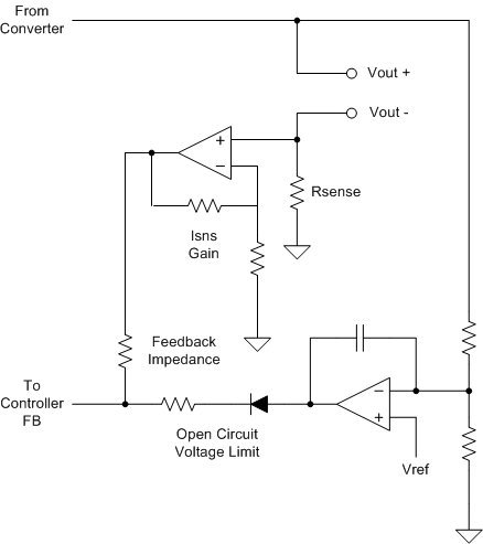
  • Here is the circuit for the feedback of a constant current supply (Generated by a constant voltage across a fixed resistor) with Open Circuit Protection limit.


    The OCV limit is imposed by an integrating amplifier monitoring a reference voltage and the output voltage.  If the scaled output voltage exceeds the reference voltage, the amplifier raises its input, forcing current into the feedback node and reducing the voltage required across the series sense resistor and thus the regulated current.  The resistors are sized such that the integrating amplifier can maintain the reference voltage on the FB pin even if the voltage drop across the Rsense resistor is zero, allowing the OCV circuit to completely shut down the ouptut current.

    The blocking diode prevents the integrating amplifier from from sinking current from the feedback pin, which would increase the regulated current and defeat the purpose of the circuit.

    The OCV circuit is selected for the outer loop because it is by necessity slower than the inner loop and accurate regulation of the terminal current is more important than tight regulation of the open circuit voltage.

  •  

    Hi Peter,

                  How are you? Sorry for the delay, actually i was busy with things these days, and the good news is that i had ordered and tested the TPS54160 EVM for High Brightness LED's and it seems to be working for my application, i have just tested it and need to clarify some issues before going ahead with the producion. All this while we had been discussing about controlling the current by means of  Vsense, which i think is a bit difficult, in the TPS54160 EVM there is an option for PWM dimming and Analog dimmimg, out of which i think PWM method would be pretty simple for me to implement. Can the PWM method provide full variation in the  load current, like the EVM provides a max load current of 700ma, so is it possible to get the 700 ma by applying a 100% duty cycle PWM ( i am also preparing to check this out).


  • Muhammad,


    PWM dimming would generate pulses of 700mA of current at the same duty cycle as the PWM diming signal.  At 100%, the average current will be 700mV.  At 10%, the average current will be 70mA, but in 700mA pulses @ 10% duty-cycle.

    Analog dimming on the other hand will adjust the DC current value using an analog input signal, similar to what we've discussed previously.

  • Hi Peter,

                          I am testing the TPS54160 EVM . I am using a Vin = 22-24V and on the PDIM pin instead of a PWM signal i have applied a DC signal from a DC source,hence my ckt is working at  max load current of 700ma approx. the voltage @ PDIM is >1.21V.  But  i am facing a problem when i try to test the ckt for long hours ,it starts giving problem, like after 1 hour or so the current stops to flow and the ckt starts to make a small switching  noise, i don't which component is makling the noise.  

  • Can you provide any waveforms of the circuit when it is not functioning properly?

  •  

      Lets see yesterday the circuit was showing those symptoms for a while, but now its working fine if it happens again i will let you. As i had told u Peter that the load of this circuit is the electrodes which are dipped in impure water, now when the ckt is on load i.e electrodes are dipped into water the o/p voltage is as low as 2.1V is that fine or can it create any problems.

  •  

    HI Peter,

                          I was thinking of another  method of controlling the current through the electrodes, can't we use a precise potentiometr in the place of our 1.2ohm/1W resistor, if we do so will it be safe.

  • You could replace the resistor with a precision pot, but efficiency would be quite poor at low currents. 

  • Thank You Peter for your unparallel support on this query of mine. Because of your support i was able to evaluate Ti product as per my end product requirement. I have been missing for the past 4 months, but that was bcoz i have been not faring well health wise, severe back pain. so i was off from work. now i would take this project on  & would definitely look on towards you PETER.     .......................Thanx Once Again

  • Muhammad,

    Welcome back.  I am sorry to hear that your health was an issue for the past several months, but am glad to learn that you are improving.


    I am glad we have been able to help you and look forward to continuing our support.

  • Hi Peter,

                           Now i am starting with the PCB design of my system. As i had told you before also that i had purchased and tested a TPS54160 Evaluation board for my application and it is working fine with it. Now i have to integrate 4 such modules on a single PCB since there are 4 electrodes. Now this system is suppose to run on 230V AC which means i will have to convert the I/P AC to DC and i wanted some ideas for the same. My TPS54160 O/P will be somewhere between 12V to 24V DC. So which is the best method, should i use a rectifier /filter at the I/P directly or should i step down the voltage with a small Transformer.


    Also i was thinking of some other applications of the TPS folio like a SMPS based 24V battery charger. But that requires a fairly high current rating like 10A & above, but the TPS is limited to only 6A with the TPS5460 is it possible to increase the current by using some other components. 

  • Your AC input solution is going to depend on your needs for isolation, power factor correction and efficiency.  Most of TI's AC input solutions are based on Power Factor Correction (PFC) solutions that draw sinusoidal input current in phase with the AC line voltage for the highest  possible power factor correction.  Generally such solutions are 50-300W, producing a 380-400V output voltage that is then down-converted with a transformer based isolated DC-DC converter such as a flyback or forward to produce the necessary voltage.  This combination provides high power factor correction, low harmonic distortion, high efficiency and isolation.


    if your application does not require power factor correction, and you will use a bridge rectifier w/ capacitor ouptut, I would typically recommend a step-down transformer before the bridge rectifier to reduce the working voltage applied to the bridge, allowing smaller diodes to be used.

    Alternately, the full line voltage can be applied to a bridge (there are many full-wave bridge rectifiers available, rated for the full line voltage) and then reduced through a high-frequency isolated DC/DC converter, taking advantage of the higher frequency of a switch mode power supply to reduce the size of the transformer (A 60Hz transformer needs to be pretty large)