My goal is to add power status LEDs to a new design. I am using a BQ24070 for Li-Ion charging and Dynamic Power Path Management. The STAT1 and STAT2 pins of the BQ24070 IC indicate various charger operations, and the \PG pin indicates when input power is present and above the battery voltage.
I am having a hard time understanding the datasheet documentation in regards to these pins. According to the documentation:
"The open-drain (OD) STAT1 and STAT2 outputs can be used to drive LEDs or communicate to the host processor. Note that OFF indicates the opendrain transistor is turned off."
and
"The open-drain pin, \PG, turns ON (low) when exiting sleep mode, and is turned off in the sleep mode (open drain).. Note that OFF indicates the open-drain transistor is turned off."
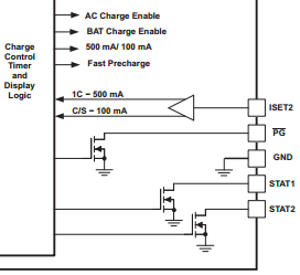
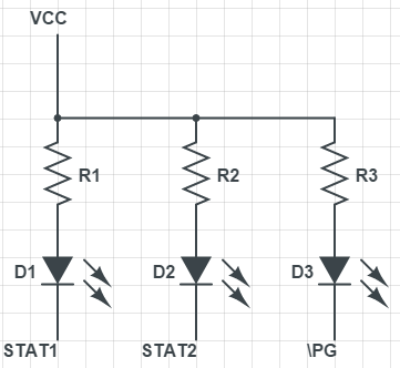
However, if you look at the Functional Block Diagram in Figure 8.2 (also shown below) of the datasheet, the STAT1, STAT2, and \PG pins are all tied to the same type of transistor. Why is the PG logic inverted? From a functional perspective, I simply want an LED turned ON when the "power is good", and when STAT1 and STAT2 are ON. Do the LED circuits below accomplish this? The documentation is quite confusing.