This thread has been locked.

If you have a related question, please click the "Ask a related question" button in the top right corner. The newly created question will be automatically linked to this question.

BQ76920EVM external MCU SMBus

Other Parts Discussed in Thread: BQ76920EVM, BQ78350

 Hello,

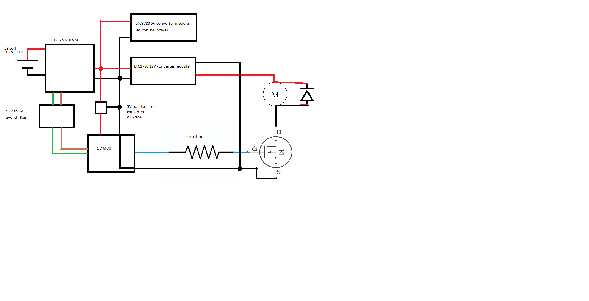
I recently bought the BQ76920EVM and I plan to to connect a 5S cell and a MCU to the SMBus pins of the BQ78350 to display informations like battery voltage.I want to put the MCU on the Pack port of the evm, so it shuts down when the EVM opens the pack output since it is only for displaying data. There is also a 12V smps on the pack pin. The MCU drives a fan from the output of the smps with a mosfet, so I have to connect the output ground of the smps and MCU to pack-. The SMBus is connected with a level shifter to the MCU. Am I going to destroy my MCU when the pack switches of or even when it is on and can I still connect my MCU to a pc to read the serial data of the MCU?

Thanks in advance

Moritz

  • If understanding you correctly,from the description of the setup, it sounds the MCU will be exposed to the  excursion of the  12V that is hanging off the PACK terminal. Typically  fans motor have quite a bit of inductive kickback at startup/reverse/stop, which may make the 12V node to fly high. please pass on the mods of the schematic on what you trying to do.

    txs

    vish

  • I added a something like a block diagram and fixed the titel :) I hope there won't be ground problems when connecting a pc to the MCU or when the EVM switches off the pack terminals and thanks for the quick answer.
  • The challenge in your system will likely be the block shown as "2.5 to 5V level shifter" since the EVM has SMBus reference to the cell negative (BATT-) while the rest of your system uses PACK negative which is switched by protection on the EVM.  On the EVM it works to demonstrate the function of the BMS subsystem particularly with an isolated notebook computer, but in a complete system something more is typically required.  As drawn I expect you may have a leakage path for continued charge or discharge through the communication lines when the EVM protection switches.  Common solutions would be to have the "2.5 to 5V level shifter" block include isolation which will require power on both sides, switch the communication path which does not allow communication during protection, or use a high side switch after the EVM circuit to keep a common ground in the system (PACK- ~= BATT- while PACK+ is switched).  

  • Ok thanks, I looked a bit around and found I2C isolation chips that also shift the voltage level. Just one more thing, will there be a problem if I connect a pc to the mcu, since it is ground referenced?
  • Connecting a PC to the MCU should not have any different leakage for the battery, however as with any system be sure you do not introduce current loops through grounding of the PC and other equipment. If your USB for the charger is from the same PC it should be OK. If the USB is from somewhere else, it is likely still OK but you may need to check.
  • Ok, thank you very much :)