This thread has been locked.

If you have a related question, please click the "Ask a related question" button in the top right corner. The newly created question will be automatically linked to this question.

TPS5430 for Output -5V/-9V from Input +12V

Other Parts Discussed in Thread: TPS5430

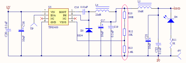
I am planning to use below schematic using TPS5430 for -5V/-9V application.

Both voltages for op-amp sensing application ( medical grade instrument ) and load requirement is not more than 50 mA.

For -5V resistors are as below:

R10=0E ,R12=47K, R13=15K

Please review circuit and suggest for any improvement.

  • It is a little complicated. TPS5430 is internally compensated, so you must select the LC filter to align with the internal compensation. For very low load current, a large inductor value will be calculated. Webench suggests that you use 100 uH for each design, with 33 uF, 386 mohm ESR electrolytic capacitor for the -9 V output and 68 uF, 200 mohm ESR electrolytic for the -5 V output.

    You could conceivably design for larger output current which will decrease the inductor value and correspondingly increase the capacitor values.
    For -9 V, 18 uH and 150 uF, 85 mohm. For -5 V, 15 uH and 330 uF, 25 mohm.

    If you were to go that route, you will always be operating heavily in DCM mode. I do not know if that is an issue for you.

    At that light load, I doubt you would need the additional LC on the output, but that is your call.

    I would recommend 10 uF ceramic capacitor between Vin and your actual GND. C18 need to be ceramic as well. It can be lower than 10 uF, but 10 uF is a good value.

    The voltage divider values look ok.
  • If it is in DCM mode, does my load will get required voltage or current or there will be drop in voltage or current ? Load is sensing circuit ( OP-AMPS) so voltage regulation must be proper..

    Is there any IC which will generate -ve voltage using +voltage (+12V)?