This thread has been locked.

If you have a related question, please click the "Ask a related question" button in the top right corner. The newly created question will be automatically linked to this question.

LM5069-1 fault timer

Other Parts Discussed in Thread: LM5069

I am having trouble with my fault timer.  

I am using the LM5069-1 as a circuit breaker and an inrush current controller on a 24V rail, with a load that has 600uF of capacitance.

i have selected 1.0uF (10%) for Ct.  the 85uA fault timer current can be 51uA to 120uA.  and the timer threshold voltage can be 3.76V to 4.16V. which should result in at fault time out of  ≈ 30ms - 90ms.

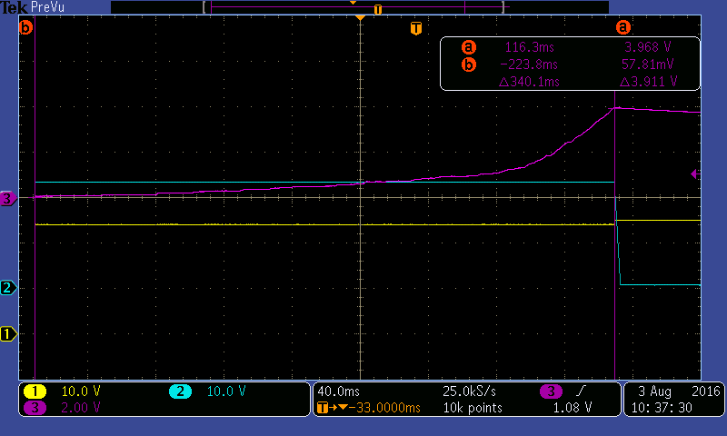
in lab i am testing this and i am measuring much longer than that.  340ms!   what am i missing here?

  • Hi David,

    How is the test being conducted? The TIMER waveform should pretty much be linear under all scenarios since it is a constant current source, constant capacitance, so I = C * dv/dt and thus dv/dt should be constant.

    In the waveform attached, the CH3 does not look constant, so I'm curious if the circuit is going into and out of fault mode (zoomed in, if you see some cyclical up/down behavior). It does not appear very steady. In general, we recommend testing overcurrent by using a high power resistive load or setting a value fairly above the current limit on an eLoad and then turning the eLoad on.

    Note that we have design tools for the LM5069 to help with component selection and calculations.

    You can check out the design tool at www.ti.com/hotswap --> "Tools & Software"

    We also have step-by-step video tutorials at www.ti.com/hotswap --> "Support & Training" which should be able to answer all questions you may have regarding the tool. If not, we would love your feedback which you can post on the E2E forums.

    Lastly, we have an application note at www.ti.com/hotswap --> "Technical Documents" --> "Robust Hot Swap Design" which discusses the detailed equations and methodology behind the design calculator tool.

    Thanks!
    Alex
  • here is an other shot of the *85uA* charge current and the subsequent *2.5uA* discharge current.  On this scale, the fault timer charge current apears to have a knee.  if i measure from that point the charge time is inside the specified range.

    note: the 2.5uA discharge should and does take ≈ 1.6sec.

  • I am using an e-load set just below my current trip point. im then using the load adjustment knob to increase the load until the fault occurs.
  • Hi David,

    I understand, and yes during that type of test procedure, you may see the device go into and out of running the fault timer.

    The way the device works, it will begin to run the timer just below the current limit regulation point. The reason is because, we want to be absolutely sure that if the device is regulating the MOSFET, then the timer should already be charging.

    If this was not designed this way, then it would be possible that the device could be regulating the MOSFET indefinitely, with the TIMER never activating.

    So if you captured the same waveform and looked at the GATE, you may not see it drop or regulate.

    If you use the same eLoad, set it a bit higher and then turn it on or hot plug it to the output, you should see the TIMER slew rate be constant.

    So what I am saying is, the timer is longer in this case because it is not truly regulating the MOSFET and is instead operating close to but below the regulation point.

    Thanks!
    Alex
  • I tried again by applying a step load, a bit above my tested trip point, to see if that made a difference. It does.

    This brings up a new question.  how is the fault triggered?  i did not expect different results from a step load and a ramp load.

  • Hi David,

    It's not quite a step load vs ramp... It is just easiest to explain that way. It has to do with how close you are to the point where the timer begins to activate.

    Basically you can still do a ramp, but if you turn the knob just *slightly* quicker, you should see the expected behavior.

    To give a more detailed explanation of the TIMER control loop, I would need to discuss our IC design team and get back to you around Friday or early next week (it has been a while since I needed to know this, I simply forgot the technical details).

    Thanks!
    Alex
  • i would be nice to know the details, but at this point, i have what i need. thank you for your help.